Directional casing while drilling applied to improve high-angle top-hole drilling from producing platform
By Graeme Dawson, Andrew Buchan, Ilen Kardani, Schlumberger; Andrew Harris, Lonnie Wercholuk, TESCO; Khairul Amir Khazali, Abdul Halim Shariff, Keith Sisson, Heru Hermawan, PETRONAS

Directional casing while Drilling (DCWD) using a rotary steerable system (RSS) or a steerable positive displacement motor (PDM) is a recent enabling technological application of casing while drilling. It has been applied in wells in the North Sea and the Middle East using both RSS and PDMs. The technology was recently used in a project from a producing platform in the Asia Pacific region. The project was completed successfully in terms of increasing ROP and lowering the time and cost to drill the top-hole section of the well.
Top-hole directional drilling of wells in high-density locations, such as multi-well producing platforms, require carefully planned procedures and reliable techniques. The procedure requires, in addition to directional capabilities, that the well meet the demands of anti-collision concerns within the torque and hydraulic operating parameters of the formation.
The successful operation led to several records:
• World’s deepest 13 3/8-in. DCWD job;
• World’s highest-angle directional well with 13 3/8-in. DCWD;
• World’s fastest rate of penetration for a 13 3/8-in. DCWD;
• World’s first application of Gyro MWD with DCWD.
As a result of this project’s success, the operator is deploying DCWD technology in another project in East Malaysia.
BACKGROUND
The field selected for the introduction of DCWD is located in the Malay Basin, about 100 miles off of the east coast of the Malaysian Peninsula, in water depths of approximately 70 m. It is the largest integrated oil and gas development in Malaysia.
Currently, the field consist of one mother platform (A) and four satellite platforms (B, C, D and E). DCWD technology was applied on D, a 16-slot, four-legged platform, and wells D4 and D3 were chosen for this application.
The formations encountered while drilling the 17 ½-in. top-hole section, which are soft and unconsolidated, have a history of severe losses. At the same time, the focus was on increasing reservoir exposure while reducing the number of wells and platforms required.
This resulted in the wells becoming higher in angle to extend the reach of the platform drainage zone and to maximize reservoir exposure. Due to these developments, the inclination in the 17 ½-in. top-hole section has increased, which compounded existing problems by degrading hole cleaning.
These hazards have been sustained in the deviated 17 ½-in. top-hole sections in previous conventional drilling campaigns with mixed results. Section times have varied from between 5 hours to 24 hours.
The operator decided to use DCWD technology to improve drilling performance while mitigating risks traditionally associated with the top-hole section. The DCWD technology to be used was a retrievable bottomhole assembly (BHA), and the objectives were:
• Improve the safety and efficiency of casing running and handling with a stabberless casing drive system (CDS);
• Prove the concept of batch casing drilling commercially and technically;
• Enable casing drilling to become the base case for drilling top-hole sections;
• Prove the directional capability of 13 3/8-in. casing drilling assemblies;
• Minimize flat times associated with conditioning and cleaning the hole in soft, unconsolidated directional top-hole sections in the field;
• Improve drilling performance in the top-hole formations though better hole cleaning with 13 3/8-in. casing versus 5 7/8-in. drill pipe;
• Log the section with gamma, resistivity and annular pressure while casing drilling;
• Casing drill from the 26-in. conductor shoe to section TD in one run.

DCWD provided the additional advantage that if mud losses occurred, the mud system could be switched to seawater while continuing to drill ahead with no time expended trying to mitigate incurred losses. Another advantage is the ability to retrieve the BHA while leaving the casing in place, thus eliminating potential casing-running problems over the troublesome formations drilled.
Two methods of BHA retrieval – wireline or drill pipe – were available. With the drill pipe method, which was used during these wells, a false rotary is required at the surface to run the drill pipe through the casing. The grapple-type latching tool locks into the drill lock assembly (DLA) and releases the dog locks when picked up, causing a bypass port to open through the seal cups in the DLA that prevent swabbing during retrieval. The BHA is pulled through the casing at nominal tripping speeds to the surface.
PRE-JOB ENGINEERING
Extensive pre-job engineering was required to ensure a successful operation. Challenges included:
• Rig requirements: Rig crews were given extensive safety and technical training prior to running DCWD. The casing drive system was used in running 13 3/8-in. and 9 5/8-in. casing in wells D3 and D4 prior to running the full DCWD application.
• Casing design: 13 3/8-in. K-55 BTC with L-80 casing grade were used in this application. The makeup torque for this casing is 13,000 ft-lbs, and torque rings were installed to increase the makeup torque to 63,000 ft-lbs. The maximum anticipated surface revolution was 50 rpm, and the maximum rotational hours was anticipated to be 30 hrs. This meant a total of 90,000 cycles on the casing. This was not anticipated to be problematic; however, the total number of revolutions should be logged, and, if necessary, the surface rpm could be reduced.
• BHA directional performance: This was a major challenge due to an almost complete lack of offset data to determine the BHA directional capabilities. Rotary steerable systems were given first consideration for use, but it was considered too risky to use a push-the-bit system due to concerns with the shallow sedimentary formations washing out and severely reducing the BHA’s achievable dogleg severity. A point-the-bit RSS was deemed to be the optimum engineering solution, but it was decided that the relative expense of such a system would reduce the economic viability of the project. Additionally, it would not allow a direct comparison between the performance of conventional drilling techniques and that of DCWD.
Due to anticollision concerns in the top-hole section, a gyro MWD system was used to reduce the risks and time associated with the conventional wireline-conveyed surface read-out single-shot gyro surveys. The operating principles of the gyro required the tool to be stationary while initializing. If an RSS system had been used to provide directional control, it would have required all the directional BHA (including RSS, MWD and gyro MWD) to be situated below the mud motor, which would have been located inside the casing string.
Therefore, a conventional PDM assembly was used to provide the directional control while allowing the collection of survey information, which were required due to anti-collision concerns. To ensure the BHA design met the unique challenges of these wells, extensive research and modeling was conducted to determine the predicted sliding dogleg capability and rotary behavior of the various BHA designs.
As such, the final BHA used showed little discernible difference from what would be seen from a conventional motor BHA on drill pipe.
• Mud/cement design: KCL/PHPA with 2% of radiagreen was designed for this application. Because a basic cement plug could not be used, it was decided to use a PDC-drillable cement retainer.
• Drilling engineering: Use of DCWD technology in these wells would significantly change the expected hydraulics and torque and drag values from those of offset wells with conventional drilling assemblies. Alterations in hydraulics were largely due to the increased internal diameter of the casing, compared with drill pipe, leading to a significantly reduced standpipe pressure.
More importantly, the reduced annular clearance between the casing and the borehole wall would lead to an increase in annular velocity and, as a direct result, ECD. Because the field had a history of severe losses in the soft sedimentary formations in the top-hole sections, accurate modeling of expected ECD values and limits was crucial to the project’s success.
Similarly, expected torque and drag values would be much higher than when drilled with conventional assemblies due to the increased casing weight and additional string borehole wall contact. This was critical to ensure that the additional torque would not exceed the torsional yield limits of the casing or the makeup torque of the connections. Also, it was important to confirm that the axial load capabilities of the casing would not be breached at any point.
To get actual values as close as possible to predicted, extensive pre-job modeling was conducted. Results were repeatedly analyzed and compared. Accurate modeling of ECD and torque and drag measurements would prove invaluable to the success of the project by providing baseline measurements to gauge hole-cleaning effectiveness and to optimize ROP to help evade excessive annular loading, which would reduce the potential for stuck pipe and excessive mud losses.
• Surveying and anti-collision: Because the DCWD wells were to take place on a live producing offshore platform, accurate wellbore surveying was critical to mitigate collision and HSE risks from surrounding wells on the drilling template. This was a particular concern because MWD azimuthal measurements are under external magnetic interference for the shallow portions of each section. Further, there was difficulty running and centralizing a conventional wireline-conveyed gyro through the 13 3/8-in. casing and the BHA.
Across the interval where MWD surveys were under magnetic interference, it was proposed that a gyro MWD tool be run below the MWD. This proved critical in enabling the surveying and steering of the DCWD sections. This project also became the world’s first successful application of gyro MWD with DCWD operations.
OPERATIONAL OVERVIEW, RESULTS
Well D4
The 26-in. conductor pipe was driven to TD at 186 m. A clean-out assembly using a 17 in.-by-23 in. bicenter bit was run into the hole, tagged the mud line at 180 m, then drilled to 190 m, 4 m below the conductor shoe. 100 bbls of KMC lift were pumped into the hole, and the clean-out assembly was pulled out of the hole.
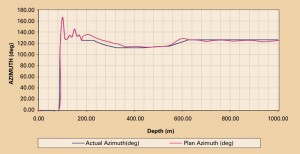
The well plan called for the inclination to build from 8.43° to 36.15° while turning the azimuth from 125° to 115°, then left to 126°. The planned dogleg severity (DLS) was 2.5°/30 m.
Following a pre-job safety meeting (PJSM), the 13 3/8-in. directional casing drilling BHA was made up. The BHA consisted of a 12 ¼-in. mill tooth bit, 12 ¼ in.-by-17 ½ in. underreamer, 9 5/8-in. motor with a 12 1/8-in. stabilizer and 1.5° bend, float sub, 11-in. NM UG stab, 8-in. gyro MWD, MWD, resistivity logging tool and an 8-in. pony non-magnetic drill collar.
The BHA was shallow-tested at the rig floor with the underreamer arms confirmed fully open at 300 gpm and 130 psi. The assembly was racked back to the derrick, and the top drive saver sub was removed. The assembly was run in the hole and the slips set at the rotary. The elevator was changed to a 13 3/8-in. side door elevator, the 13 3/8-in. shoe joint, pre-loaded with the 13 3/8-in. DLA and made up to the directional BHA. This was run in hole, and the slip joint was set on the pup joint above the casing profile nipple (CPN).
The CDS hydraulic service loop was hung at the derrick, and the 13 3/8-in. CDS and PS-500 power slips were rigged up. The assembly with 13 3/8-in. 54.5 lb/ft K-55 BTC was run to 190 m. The crew commenced casing drilling at 190 m with 600-700 gpm drilling fluid at 50 rpm. The angle built from 8.15° to 11.72° at 247 m. Flow rate was increased to 700-1,050 gpm, and drilling continued, with sliding as required, to 623 m. An inclination of 37.9° was reached at 508 m, with a tangent section being drilled from that point.
High drag was noticed at 623 m, so 60 bbls of KMC lift were pumped and circulated out. The radiagreen was increased from 2% to 3% by volume. Casing drilling operations continued to 752 m with a flow rate of 1,050 gpm at 50 rpm and 30 bbl of KMC lift pumped every five joints.

Total losses occurred at 752 m. The decision was made to pump 80 bbl of loss control material (LCM) to regain returns. The attempt was unsuccessful, and it was decided to switch to seawater. The crew drilled ahead to a TD of 1,005 m with no returns at 1,100 gpm and 50 rpm. 30 bbls of KMC lift were pumped every three joints to TD.
The switch to seawater meant that the signal from the MWD was significantly weakened. Different bit rates for the MWD were tried with little improvement. It was decided to take delayed surveys, which meant that the MWD began sending the survey after a specified time interval once the pumps were restarted after connection time. This improved the MWD signal significantly.
The casing drilling BHA drilled a total of 815 m. Total bit time was 9.95 hrs for an average ROP of 82m/hr while building inclination from 8.4° to 36.88°. A final survey was made at 36.88°, and 100 bbls of KCM lift were pumped into the hole and circulated, cleaning the hole four times from the bottom up.
The pump-down retrieval tool (PDRT) was launched and pressured up to 600 psi to release the DLA. 5 7/8-in. drill pipe was run to the top of the DLA and latched into the PDRT. When it was confirmed that the BHA was engaged by the drill pipe, it was pulled out of the hole.
Directional performance: The required DLS of 2.5°/30 m was achieved at the start of the section using 100% sliding mode. As the build-up curve was established and the formation became more competent, the sliding percentage was reduced, with a slight build tendency observed. Sliding was continued with steady toolfaces being maintained and no hanging up. Once at the inclination required, the assembly showed a slight dropping tendency in rotary mode. The slide/rotate ratio on this well was approximately 50/50 to build trajectory with the motor assembly.
Drag trend: The drag trend charts indicated that, at 521 m, the drags began to deviate from the trend, caused by cuttings build-up in the annulus with 2-3 cm clay balls. At 631 m, it was decided to circulate the hole clean. Drilling continued to 751 m. The drags were higher than planned, yet appeared to be trending with the planned values. At 751 m, total losses were encountered, and the well was completed with seawater, at which point the drags began trending downward as the clay balls were dispersed.
Torque trend: Torque increased at 521 m, the same point where the drags deviated from the plan. High break-over torque was experienced after the connections, indicating some sort of differential pressure sticking, possibly caused by the higher equivalent circulating densities (ECD). Once casing drilling with seawater commenced, the torques trended per plan, and there were no significant break-over torques to regain rotation after connection.
ECD: ECDs recorded by the MWD tool showed that, from the onset, the actual values did not trend with the plan. After sliding without rotation at up to 100 m/hr instantaneous ROP, cuttings were loading up the annulus. Cuttings coming over the shakers were typically 3-4 cm clay balls while casing drilling with mud. The ECD spiked at a maximum 12.5 ppg, typically 2-3 ppg above the mud weight. The peaks also corresponded to the 30-bbl high-viscosity sweeps pumped every third joint. At 751 m, where circulation was lost, the ECD dropped significantly, and the trend flattened out for the remainder of the section drilled.
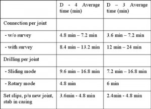
ROP performance: This well was drilled with 9.2-ppg KCL PHPA mud with a 30-bbl high-viscosity sweep every third joint. The ROP was initially 30 m/hr and increased up to 180 m/hr. Average sliding ROP was 63 m/hr, and 119 m/hr rotating. The average on-bottom ROP was 82 m/hr over the 815 m casing drilled.
WELL D3
In this well, the plan called for the inclination to build from 11.6° to 58.11° and turn azimuth from 186° to 196°. The planned DLS was 2.5°/30m.
The deviated 26-in. conductor pipe was driven and cleaned out as in the previous well. Similarly, the BHA was made up along with the CDS hydraulic service loop and tested. With all components successfully tested, the assembly was run in hole.
Drilling commenced with reduced flow rates and 100% sliding to gain the required DLS in the soft formation. At 789-m MD, the required inclination and azimuth were achieved, and a tangent was drilled from that point.
The section was drilled to TD at 1,201 m with approximately 1,000 to 1,100 gpm at 50 rpm with a 30-bbl high-viscosity pill pumped every third joint. Total bit time was 10.05 hrs for an average ROP of 100 m/hr. The final survey indicated an inclination of 58°.
Directional control: There were no issues sliding with seawater. The rotary/slide ratio was 51/49. The assembly had a reduced drop rate at a higher inclination of 0.9°/30m.
ROP performance: The initial ROP of 60 m/hr increased to a maximum 195 m/hr over the section. The average ROP sliding was 96 m/hr and 106 m/hr rotating. The average on bottom ROP was 100 m/hr over the 1,011m casing drilled. This well had consistently higher average ROP, due in part to the lessons learned from the first well.
Drag trend: Because this well was drilled with seawater from the outset, the drag charts indicated no problems while directionally drilling and building the section to 58° inclination.

Torque trend: The actual torques were significantly more consistent with the planned torques compared with the segment of Well D4 drilled with mud. No high breakover torque was experienced in this well.
ECD: ECD trends were very close to the plan, with all spikes corresponding to the 30-bbl high-viscosity sweeps every third joint. The cuttings size and volumes at the shakers were dramatically lower compared with those recorded over the same interval in Well D4 while drilling with mud. Well D3 required about 50% sliding to achieve the trajectory. However, using seawater, which disperses the clays, there were considerably less cuttings through the section.
The operator plans to use seawater to casing drill the 17 ½-in. top-hole sections during future operations. Depending on the rig, the sweeps could be optimized so that 10 bbl are pumped every joint instead of every third joint, which would reduce the peak ECDs experienced.
PROJECT HIGHLIGHTS
Extensive pre-planning on both wells ensured the successful implementation of directional casing drilling operations. The rig crew was able to adapt to a “different way” of drilling, assisted by job safety analyses and toolbox talks. No modifications to the rig were necessary to implement directional casing while drilling. Well D4 was casing drilled to 37.9°, the highest angle ever achieved with 13 3/8-in. casing. Well D3 bested that record, achieving an inclination of 58°.
Gyro MWD was successfully deployed for collision avoidance. Casing drilling resulted in superior hole-cleaning versus conventional drilling operations with drill pipe. Casing drilling with seawater with 30-bbl high-viscosity sweeps was effective, with no issues on hole-cleaning or directional performance. All directional objectives were met while drilling with 13 3/8-in. casing.
Record ROPs were achieved on the two wells, reaching an average ROP of 82 m/hr for the first well and 100 m/hr for the second.

The pump-down retrieval tool (PDRT) was successfully deployed to hydraulically unlock the DLA and swallow the BHA with the casing and wash the hanger into the wellhead. The crew successfully hung casing in the wellhead on both wells. Total time savings versus AFE was 3.9 days for the two-well batch set.
PROJECT LOWLIGHTS
Well D4 was initially drilled with a KCL PHPA mud, inhibiting clay dispersal. 3-4 cm balls of clay were observed at the shakers, with instantaneous penetration rates of more than 120 m/hr. Extensive sliding meant that the hole was loaded with cuttings. Eventually, the ECD spiked at 12.4 ppg, the formation was broken down, and losses were taken.
Failure occurred when cementing through the composite retainer. This led to a fish being left in the hole. The time and cost savings accrued during the implementation (3 ½ days) was lost during the remedial work required to recover the slot. While the problem was not the fault of the casing drilling operator, it is a part of the overall system. As a result, the wells were considered technical successes only.
On Well D3, failure to properly set the DLA on surface required the BHA to be round-tripped to change out the DLA, resulting in a 12.5-hr nonproductive time event. Additionally, using seawater as the drilling fluid with 30-bbl high-viscosity sweeps every third joint caused problems with MWD detection, and time was lost at connections with missed surveys. This was rectified by delaying the survey transmission to surface, thus allowing the mud system to stabilize and improving the signal-to-noise ratio.
LESSONS LEARNED
Directional casing drilling
Alignment with other service providers on the job regarding the directional objectives and drilling performance prior to and during the job was essential. Pre-phase meetings ensured that directional drillers understand the objective, which was ROP performance.
There were no issues with directional control during the job, with the driller able to build and turn the well trajectories to 36° on Well D4 and 58° on Well D3, which was the world’s first directional casing drilling well to reach that angle with 13 3/8-in. casing.
Casing drilling with a motor assembly experienced dropping tendencies in soft formations. Steady toolfaces were experienced while sliding, with no hang-ups in either well from 36° to 58° with 13 3/8-in. casing.
There were no issues with the first implementation of gyro MWD in casing drilling for surveys and collision avoidance, nor with running LWD with real-time gamma, resistivity and pressure while drilling. Monitoring torque and drag trends while casing drilling is essential for success.
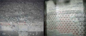
Casing drilling with mud resulted in no MWD signal issues. With seawater, however, detection issues were encountered for surveys and real-time data retrieval. In future wells, the modulator gap should be reduced in order to increase the pulse size for drilling with seawater. Reducing the pulsation dampener pressure to improve signal detection on the surface should be examined. Operators should challenge the need for real-time gamma and resistivity data for the sake of faster connection times.
The directional assembly should be modeled to reduce or eliminate the dropping tendency during rotary drilling.
Retrievable BHA
On both wells, the PDRT was successfully deployed to unlock the DLA, then swallow the BHA and wash the casing hanger into the wellhead. On both wells the PDRT was volumetrically displaced using a pump efficiency of 97%. On both occasions, the tool landed early. In the future, a 100% pump efficiency for displacement calculations should be used.
Unusual wear to the top and bottom packer cups occurred on jobs where the PDRT was used. It may be consistent with washing over the BHA with the casing. On Well D3, the casing had to be rotated. In the future, all packer cups will be drilled to ensure no pressure lock between the cups.
A dropped-object incident occurred while loading the PDRT into the casing stump on Well D4. The C-plate used to land the PDRT in the casing stump fell from a height of approximately 2 m. A lock bar was then incorporated.
On Well D3, the BHA was made up on the rig floor where the DLA was loaded into the casing and set with the mechanical setting tool (MST). All indications on surface were that the DLA was properly set. The assembly was run in hole and at the conductor shoe. On breaking circulation, there was no pressure. In future operations, the DLA will be checked visually and with flow.
The MST should not be used for locking the DLA. The DLA will be manually locked using the locking cap, allowing operators to see at the rig floor that the tool is locked properly into the profile nipple.
The MST worked as per operating procedures, and the DLA was successfully locked into the casing profile nipple at depth. The mechanical retrieve pulling tools and the mechanical pulling tool were used to successfully recover the BHAs. Installation of the 13 3/8-in. torque rings at the well site was challenging. This should be done at the shore base if possible. On future wells, it is recommended to continue the use of the PDRT to unlock the BHAs at TD.
Drilling fluids
Casing drilling was performed on Well D4 with 9.2-ppg to 9.4-ppg KCL PHPA mud with 2% lubricant. The mud inhibited reaction with clays as the crew observed 3-4 cm clay balls at the shakers while directional casing drilling. Casing drilling with the motor assembly requires a slide/rotary ratio of 51/49 to achieve trajectory. ROP with conventional drilling methods was 60 m/hr, compared with 82 m/hr during directional casing drilling operations.
ECDs were 2-3 ppg over the mud weight. High break-over torques of up to 35,000 ft/lbs were required to begin rotation. Drags deviated from the trend, requiring the crew to stop and circulate. The formation eventually broke down when ECDs spiked at 12.4 ppg. Initially, the crew attempted to cure the losses. In the future, if losses exceed 200 bbl/hr, mud should be switched out with seawater.
In Well D3, seawater was used as the fluid from the outset. There were no sliding issues, and ROP reached 100 m/hr.
ECDs were 1.5 ppg over the mud weight. At TD, the mud was displaced to 9.2 ppg; however, the crew encountered differential sticking issues trying to run the casing hanger. Switching back to seawater mitigated sticking, and there were no other issues.
Cementing
On Well D4, the composite cement retainer was used to perform the inner-string cement job. The wellhead pack-off was not run prior to attempting the pressure test. The inverted packer cup tester was not used, and the crew had to pull out of hole to rectify the situation. The hole packed off prior to cementing, and a squeeze job was attempted. The problem occurred during this operation, and the running tool became stuck. The crew backed out of the running tool stinger, and the fish was left in the hole.
A “poor boy” cement job was performed on Well D3 by under-displacing the cement and dropping the top plug only. Pressure was held for 5 ½ hrs. The crew pumped 50% excess, with no returns to the surface. The cement bond log indicated good cement to 200 m, 14 m below the conductor. Cement was drilled out with the 12 ¼-in. rotary steerable assembly and the required formation integrity test until 13.2 ppg was obtained.
On future wells, it is recommended to use the poor boy cement method and explore cementing offline in batch-drilling mode. Procedures for composite retainer cementation jobs should be reviewed if this method is planned to be used, including the use of inverter cup testers, psi tests, etc.
OTC 20880, “Directional Casing While Drilling (DCwD) Heralds a Step Change in Drilling Efficiency from a Producing Platform,” was presented at the 2010 Offshore Technology Conference, 3-6 May 2010, Houston.




Thank you for article related to directional drilling. Its really an useful information.