Expandable liner system mitigates geological challenges, predictably maintains hole size in Ekofisk wells
Expandable system proved to be key enabler for ConocoPhillips as it redeveloped parts of Greater Ekofisk Area
Drilling the lower overburden section in specific parts of the Greater Ekofisk Area (GEA) in the Norwegian North Sea can be very troublesome. Wells in these parts may intersect shales with high gas content in the upper section (requiring high mud weight) and unstable zones with massive circulation risk (requiring low mud weight) near the base of the interval.
These challenges have brought forth the need for a contingency drilling liner to “split” the section in two parts. Rather than changing the basic well design, ConocoPhillips fronted the development of an 8 ⅝-in. expandable drilling liner with high collapse resistance for this purpose. This string provides an 8.514-in. post-expansion drift inner diameter that can accommodate an 8 ½-in. bit size for the reservoir section, which is critical for the GEA well design strategy.

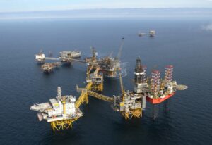
The Ekofisk field is a large chalk formation located 300 km southwest of Stavanger, Norway. It was the first commercial field to be developed in the North Sea, with first oil coming in 1971. Since then, more fields such as West Ekofisk, Tor, Eldfisk and Albuskiell have been discovered in the GEA. Ekofisk and Eldfisk are the largest fields in this area and are still considered to be the backbone of GEA production today.
The large volumes produced from the GEA have caused reservoir compaction and associated seabed subsidence. As hydrocarbons are produced and the reservoir pressure declines significantly, the effective stress increases, causing the chalk to compress and leading to an irreversible deformation called pore collapse. The resulting compaction from the pore collapse in the reservoir is transferred to the overburden, ultimately causing the seabed to subside.
Well design in GEA fields has evolved over the years to adapt to the challenges related to compaction, particularly in the lower overburden and reservoir section. However, it was not until the occurrence of subsidence was identified that it became apparent that the combination of compaction, subsidence and overburden elongation were the main causes of well deformations.
GEA drilling challenges
ConocoPhillips began a new phase of Ekofisk and Eldfisk field development in 2014. On Ekofisk, the Ekofisk Zulu wellhead platform (EKOZ) provided 35 new production slots, while Victor Alpha provided four new subsea water injection wells. On the Eldfisk field, an additional 39 production and water injection slots were provided on the new Eldfisk Sierra integrated field center (ELDS). Each project also included a cuttings and slop reinjection well.
For the EKOZ and ELDS re-development campaigns, the lower overburden section was particularly challenging. Pore pressure began to increase as drilling continued through the overpressured Miocene shale, usually drilled with a mud weight of 14.2-14.4 ppg. Once drilling into the Middle and Lower Miocene, high readings of gas would often be observed in the mud column. The presence of gas pockets between the Middle and Lower Miocene is a well-known phenomenon in Ekofisk and Eldfisk. These pockets are a combination of in situ gas and gas that has migrated from the reservoir. The gas is not producible, and handling high gas content in the mud often creates drilling challenges.
The best practice established for the field in this situation is to shut-in the well and circulate the gas out through fully opened chokes via the mud-gas separator. This may need to be repeated many times as drilling progresses, until the near-wellbore gas accumulations are vented out. This method does not follow conventional well control methods; however, historically it has been the most efficient and safest method to handle high gas concentrations in the drilling fluids. Weighting up the mud to above 14.7 ppg typically induces losses and ballooning effects, bringing even more gas into the wellbore.
Drilling the reservoir hole section also brought about difficulties caused by pore-pressure differentials. Continuous water injection increased reservoir pressure in some, but not all, areas. Due to water weakening, compaction of the reservoir continued in the waterflooded areas, even though the reservoir was repressurized by seawater injection.
At the same time, a combination of unequal distribution of reservoir repressurization, waterflooded areas and faults made the drilling window in the reservoir narrower, which made it more difficult to reach remote targets. As a rule of thumb in GEA fields, a reservoir split is usually required when the expected static differential pore pressure along the reservoir section exceeds 2,000 psi.
Expandable drilling liner
The complex conditions seen in the lower overburden and in the reservoir raised the need for a drilling liner to split the sections. A thorough analysis was carried out on a well-by-well basis to evaluate the need for the drilling liner, either as a contingency solution or as part of the planned well design.
The 8 ⅝-in. expandable liner became an attractive option in these instances. In 2011, ConocoPhillips requested development of a higher-collapse-rated 8 ⅝-in. expandable system to fit the expected drilling load cases in the Ekofisk lower overburden section. First delivered in 2012, the system consists of five main components:
• Shoe;
• Launcher with expansion cone;
• Expandable pipe;
• Anchor hanger; and
• Inner string with debris cup.
The standard practice for installing the expandable liner on a well in the GEA first involves running the expandable pipe in the hole after the shoe and launcher. The expandable pipe is made up with the pin-end facing up to facilitate connection integrity during the expansion process. A sacrificial sleeve is installed on the pin prior to stabbing on the box connection for the next joint. Once the anchor hanger is made up and run in hole, a false rotary table is installed on the drill floor. A 5-in. inner string with debris cups is then run and screwed into the safety sub above the launcher. Above the anchor hanger, the inner string is crossed over to the drill pipe.
The expandable liner system is then run to the planned setting depth with the full liner weight hanging on the expansion cone. The liner shoe is typically set 5 to 10 ft above the hole total depth in anticipation of the liner expanding down into the open hole.
A cement job is then performed by pumping spacer, followed by a cement slurry. Due to the small annulus volume, only a single tail slurry can be used. To avoid getting cement slurry falling into the top of the expandable liner, the planned cement volume is set to 75% of the post-expansion annulus volume. The thickening time of the slurry is extended to safely allow the expansion process to be completed at a speed of approximately 350 ft/hr. A dart and foam balls are then dropped and displaced by mud. The liner is rotated to a maximum of 20 RPM but stopped 5 bbl before the dart seats.
To expand the pipe, it is important to pump until the dart bumps. No cement is pumped for very short liners where the calculated cement volume is so small that there is little chance of getting quality cement in place. In those instances, the liner is expanded in mud.
Once the dart bumps and no flowback is observed from the annulus, the expansion process is initiated by pressuring up the drill string to approximately 5,500 psi against the dart. The string weight drops as the liner begins to expand. The pipe expansion is achieved by the force generated from the pressure below the expansion cone, and that process is continued by pressuring up to 3,500 psi at 2-3 bpm while pulling the drill string and maintaining the hookload below the total string weight.
The pressure is bled off slowly prior to breaking the connection and racking the drill pipe stand. This process is repeated until the first two elastomers on the anchor hanger are expanded. At this point, the rig pumps are shut down, and the overpull is increased up to 200 kips to complete the remaining anchor hanger expansion mechanically and exit the top of liner with the cone. Using more mechanical rather than hydraulic force decreases the pressure to be released from underneath the cone when the cone exits the liner top. Finally, the well is reverse-circulated clean, and the expanded liner can be pressure tested.
The expansion process will cause a shrinkage in length of about 3.5-4% (from the top down if the pipe is free, or from the bottom up to a stuck point if the liner happens to be stuck). Hence, the 8 ⅝-in. tally and the 10 ¾-in. shoe track length have to be planned accordingly to ensure the 8 ⅝-in. hanger is anchored inside the 10 ⅝-in. liner after the expanded liner has shrunk and sufficient hole is drilled below a minimum casing setting depth in case of bottom-up shrinkage.
The first 8 ⅝-in. expandable liner system was installed successfully on EKOM, a production and process platform on the Ekofisk field, in 2015. Since then, ConocoPhillips has installed 27
8 ⅝-in. expandable liners and three 6-in. liners in the GEA. The total expanded length is 33,300 ft, with an average length of 1,140 ft per wellbore. These installations were done without compromising the 8 ½-in. hole size for the reservoir section, which makes two additional contingency strings available in case other difficulties arise while drilling the reservoir.
So far, the installations have been a success. There have been no HSE incidents, system failures or failures to expand, and the liners have been one of the key enablers to overcoming drilling challenges often seen in the area.
Section efficiency (measured in ft/day) has generally been on the rise since the first installation. While including a split section adds days to the wells and lowers the well’s overall performance, the variance is not huge, and the split provides a more predictable outcome for wells placed in trouble areas in the field.
The main disadvantage of the current well design with the contingency expandable liners is the need for odd hole sizes and underreaming in every hole section. Tools have been developed to address these issues, but near-bit and string reamers complicate the bottomhole assemblies (BHAs) and compromise the bit’s cutting efficiency. The induced BHA vibrations may lead to premature tool failures, which impact well delivery efficiency.
Also, installing this type of drilling liner requires several operations – drilling the hole, keeping it open, running the liner, cementing the liner, expanding the liner, and pulling the liner out with a setting string – and each task requires time. This system may be outperformed by one-trip steerable drilling liner systems in the future.
Room for improvement
Despite the high performance achieved by the expandable liner so far, ConocoPhillips has identified areas for improvement.
Concerns were raised after one well required 11 hours of drilling time to exit the liner. Some pieces of aluminum junk were recovered at the surface on the shakers. These pieces were confirmed to be part of the liner’s transition nose. It was suspected that pieces of similar size may have affected the drill-out performance by spinning on the bottom and preventing the bit from biting.
The 8 ⅝-in. expandable liner shoe consists of three components: a composite flapper valve, an aluminum transition nose and an eccentric shoe. A study investigating previous drill-outs showed inconsistent performance. It is difficult to pinpoint the exact cause since different types of eccentric shoes have been used. The bit types used were also different, and different drill-out parameters were employed as recommended by the bit supplier. The bits were selected for optimum performance (ROP and longevity) in the reservoir layers, not for shoe drill-out efficiency.
The 8 ⅝-in. expandable liner supplier responded by modifying the design of the aluminum transition nose. This new transition nose, combined with the filament shoe, seems to have reduced the drill-out time to an average of two hours, which is comparable to conventional shoes.
There have also been issues identified when running a 7 ¾-in. liner through the top of the 8 ⅝-in. expandable liner hanger in three wells to date. The liner had to be pulled and re-run without any centralizers. The suspicion is that the fairly square ledge at the top of the liner hanger prevented the centralizer from passing through the liner. A redesigned liner top taper is being evaluated.
In many circumstances, the current 8 ⅝-in. expandable liner does not pass casing design criteria for GEA production load cases due to lower post-expansion collapse rating. The anchor hanger elastomers are also not yet ISO 14310 V0-tested. Therefore, based on operator requirements and NORSOK D-010 standards, the liner is not qualified to be used as part of the well barrier elements.
Currently, the 8 ⅝-in. expandable liner installed in GEA wells has always been covered up by an internal reservoir liner that has a barrier-qualified liner hanger. The production packer then has to be set further up in the 10 ¾-in. liner compared with a production packer in a standard well design. This may be a critical issue in the case of poor cementing behind the 10 ¾-in. liner.
There are a couple of positive effects to having a barrier-qualified liner and anchor hanger combined with good cement behind the expandable liner.
First, the length of the 5-in. liner can be made shorter, which will reduce the cementing equivalent circulating density, thus reducing the risk of losses during the 5-in. liner cementing. Second, the production packer can be set deeper, which means the gas lift mandrel can be installed deeper to provide better lift efficiency should it be needed.
A combination of expandable liner and swell packer application in GEA wells will possibly be beneficial for zonal isolation purposes in the weak zone where the probability of getting a poor cement job is high. For example, it can be used as open-hole expandable liner clad across the expected weak zone on the top of the Ekofisk reservoir or in the reservoir section.
This application requires further evaluation and planning. The open-hole swell packer may require thicker elastomers, which will contribute to significant rheological and mechanical friction during running of the liner in long-reach wells. It is also important to test and evaluate the compatibility between the swell packer and the completion and stimulation fluids in the well. This application may also increase the run efficiency as cementing is not required.
There is an additional opportunity for an expandable drilling liner that would provide the same drift size as a previous casing/liner drift. For GEA wells, an expandable liner that can extend the 7 ¾-in. liner (6 ½-in. drift) to isolate the trouble zone while providing a continuous drift would be beneficial to reach even further reservoir targets. In 2019, ConocoPhillips and the supplier developed this solution. However, the first installation did not go as planned. The investigation, evaluation, improvement and planning for the next installation is being carried out. DC
This article is adapted from SPE/IADC 204018, “Successful Installations and Predictable Performance of Solid Expandable Drilling Liner in Greater Ekofisk Field, Offshore North Sea,” presented at the 2021 SPE/IADC International Drilling Conference, 8-12 March 2021.


