Rethinking approach to testing, design of MPD choke control systems may lead to simplification
Industry also would benefit from standardizing, benchmarking choke control systems for choke characteristic response with two-phase flow
By Babak Akbari, Louisiana State University
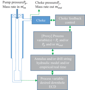
As Managed Pressure Drilling (MPD) techniques start to mature, systems developed to control one of the most important components of the system – the choke valve – become the leading edge insofar as the ability to control the annulus pressure profile. Given the increasingly narrow and challenging pressure windows, particularly those encountered in deepwater, the importance of precise and repeatable control of annulus pressure becomes paramount. Figure 1 illustrates a general paradigm for MPD choke control.
Choke control systems, basically process control valves, have been around for some time, especially in the downstream segment. However, depending on the service provider, their under-the-hood workings may be different.
Regardless, a zoomed-out view of such systems includes a choke feedback control loop that seeks to maintain a process variable at a desired set point. This would normally, though not necessarily, be choke pressure; it could be mass rate out or even the pump pressure. In the schematic, this is called the “proxy” process variable because the true process variable to be controlled is the equivalent circulating density (ECD) profile in the open-hole annulus (or the ECD at a select “anchor” point).
The link between the two variables may be provided by (a) hydraulic models (for the annulus or drill pipe, depending on which pressure is taken as the proxy variable; or a combination); or (b) well compressibility models (using overall pressure and mass rates in and out); or (c) it may be provided purely empirically and in real time (e.g., small influxes/losses); or (d) a hybrid of the three. Regardless of the algorithm used, the system’s functionality, in practice, comes down to how repeatable and accurate the control system manages to maintain the open-hole ECD profile within the desired limits.
Figure 2 proposes a paradigm that can be implemented in currently available control systems (if not already) and in the testing phase of such systems. The basic premise of this paradigm is the separation of choke characteristic response and that of well hydraulic response. In the author’s experience, the two system components behave in such a fundamentally different manner that a control system – whether a simple Proportional, Integral, Derivative (PID) or other/non-linear – could not be properly tuned to a combined response.
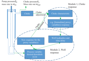
Even if it did, further diagnosis would probably be much more difficult compared with a control system that works in series by, first, determining the immediate response of the proxy variable (mass rate out or choke pressure), then determining if further adjustment is needed when the immediate action’s pressure wave has propagated through the well and back.
This second part would be where a well hydraulic model may be needed. The subsequent choke adjustment(s) would have another immediate proxy variable response, and the cycle continues. Module 1 here is that of choke immediate response, and Module 2 is the well response as seen in Figure 2.
Another advantage of modularizing such control systems is that, given the operation, the choice of right proxy process variable(s) can effectively eliminate the need for a Module 2. A couple of examples are:
• Kick circulation using Driller’s method: After pump start-up, pump pressure Pp, can be chosen as the proxy process variable. It is well accepted that, at this stage, constant pump pressure can be reliably used as an indication of constant bottomhole pressure. With that, Module 2 is effectively reduced to reading the pump pressure.
• Containing pressure during connections: In order to trap the lost annular pressure during connections when the muds are turned off, the flow differential min–mout can be chosen as the proxy process variable, which again eliminates the need for a hydraulic model.
In circumstances where the use of a hydraulic model is inevitable, this modularization helps in decoupling what one could describe as the immediate effect of choke adjustment (a function of choke characteristic, based on its Cv coefficient) and the delayed response of the well.
As a numerical example, consider drilling ahead at 3,500-ft water depth with last casing-setting depth at 15,000 ft; currently drilling at 17,200 ft with 600 gpm, 15.4 ppg synthetic-based mud (SBM) density, and 100-psi surface backpressure. According to the hydraulic model, the ECD at the anchor point is 15.88 ppg and an adjustment to 15.92 ppg is desired, due to increasing pore pressure, which is equivalent to a 36-psi surface backpressure increase. Among other methods possible in implementation of a modular control system, possibly the simplest one is described here.
The control system of Module 1, which is the choke characteristic and is tuned separately, makes a choke adjustment resulting in a 36-psi increase in the choke pressure, which is taken as the proxy variable in this case.
In this case, assuming the SBM that is nearly twice as compressible and twice as dense as water (in ambient conditions), then the speed of travel of compressional wave in the mud is nearly half of that of water in ambient conditions; i.e., almost 2,300 ft/s.
In this simplified case, Module 2 is essentially (a) the lag time between choke and pump and (b) pump pressure. In other words, 17,200×2/2,300s ~15s wait time is needed before any sort of well hydraulics based control system (Module 2) kicks in. At that point, the model (in this case it’s the pump pressure increase) indicates whether an additional choke adjustment is needed.
In this case, for simplicity, the presence of a hydraulic model is ignored, and it is assumed that a 36-psi pump pressure increase would result in a 36-psi downhole pressure increase, which would satisfy the annular pressure set-point. In other words, our hydraulic “model” is essentially the pump pressure reading.
For example, and to put it in perspective, a more accurate pressure drop, by only accounting for the extra hydrostatic pressure increase in the drillstring as a result of the SBM fluid compressibility of 2.16×10⁻⁶psi-1, would mean that the extra hydrostatic resulting from the 36-psi extra pressure increase in the entire drillstring would be just shy of 1.1.
It should also be considered that some of this extra hydrostatic head will be offset by the increase in frictional losses due to the slightly higher density. Therefore, the debate is over something less than a 1 psi difference, in this case.
Further, although the pressure wave fronts start to be received in surface transmitters after 15s, further major changes in pressure tend to be non-continuous and arrive at nearly 15s intervals. The pressure changes will progressively weaken and die down after a couple of cycles. It may be beneficial if Module 2 takes this into account in its tuning process, e.g., if it uses a PID controller, with relatively weak gain and almost no derivative along with a strong integral set of parameters may work the best in such system.
If further adjustments are needed, the process repeats (step 1, then step 2) until the model (pump pressure, in this case) arrives at the desired set point.
It must be emphasized again that the term “model” is used loosely here. It could be as simple as a pump pressure transducer reading or as complex as a model for annular flow of multiphase non-Newtonian cuttings-loaded fluid that also considers pipe eccentricity and rotation. The main point is that modularity helps in picking and choosing what could be the best (a) proxy variable and (b) “model” for the particular circumstances and given the available resources.
As another example, if pressure while drilling (PWD) readings are available, the only thing remaining within Module 2 would be to account for the lag time.
Existing Choke Testing Capabilities
One method to benchmark and test the functionality of the control systems is to test the choke control system in a real well with downhole instrumentations. The problem is that, in the testing phase, the capability of the choke control system to maintain the bottomhole pressure within a desired set point is evaluated all at once. As explained, this is problematic in the diagnosis and tuning of any system’s inner workings. The choke characteristic behavior or Cv (flow % versus choke opening) and the well hydraulic response, in such a setup, would be inseparable.
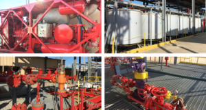
The Louisiana State University (LSU) Petroleum Engineering Research and Technology Transfer (PERTT) Laboratory is equipped with full-scale facilities, including positive displacement pumps, tanks and pressure control equipment, and cased wells providing a closed-loop circulation system. Aside from hands-on well control training that the facility offers to students, the facility hosts outside companies, including those who want to test their pressure control equipment.
The facility’s modular infrastructure allows installing/retrofitting pressure control equipment and flowing fluids through the wells. As the facility’s staff become acquainted with well control procedures and pressure control schemes and state-of-the-art automatic chokes, the facility’s capability to host more complicated circulation/pressure control scenarios is enhanced. This is occasionally instrumental in keeping the well control lab of LSU up to date with the most recent advancements in technology when companies’ confidentiality terms allow. LSU PERTT Lab’s objective is to provide momentum to this synergistic cycle.
One of the objectives of LSU PERTT Lab is to provide the infrastructure for benchmarking pressure control systems using standardized procedures and developing customized diagnosis tools. PERTT Lab is equipped with six wells, which are cased all the way to bottom.
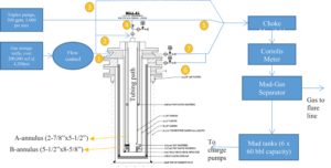
Normally, Wells #1 (2,800-ft TVD) and #2 (5,800-ft TVD) are used for circulation and well hydraulic tests. Well #1’s configuration is shown in Figure 3, along with flow paths. It is operational and has circulation capability.
Currently, Well #2 is under workover operations to change its wellhead and current tubular structure. Wells #3 through #5 are normally used for gas storage to inject kicks at the bottom of the test wells; however, occasionally, they are used for other downhole product testing. Well #6 is not operational at this time and is mainly used for demonstrating the equipment that can be nippled up on its wellhead.
The facility, given preparation time, is capable of performing choke control tests in various configurations. In fact, the setup facilitates tests and switching between tests of Modules 1 and 2 as needed.
For instance, several options exist to test a choke control system in Module 1 mode, (if in single phase, this is fundamentally an ANSI/ISA-S75.02 standard test) as follows:
• Single-phase liquid flow path bypassing the well, path number 5: This path’s hydraulic length is around 80 ft (length of lines from triplex pumps to the choke manifold), which means that the choke adjustment waves take 0.03s to bounce back to the choke. This is fast enough of a response to help isolate other hydraulic effects from the actual choke characteristic response. PERTT has already had customers test their choke control systems in this mode. A maximum of 500 gpm flow rate can be achieved; however, depending on choke backpressure, this amount may be less. Given the low liquid storage capacity needed to flow thorough this system, the facility can also potentially test other non-Newtonian fluids in this configuration.
• Single-phase gas flow path bypassing the well, path number 3: Same as the single-phase liquid but with limited applicability to MPD, given the fact that single-phase gas flow is rarely encountered. Given the ability to, theoretically, apply over 4,000 psi pressure upstream, supercritical flow would be expected. This test may be of interest in the context of underbalanced drilling applications.
• Two-phase flow path bypassing the well, paths 5 and 3 commingled: This would require a method of commingling the flow from gas storage system and pumps and eliminating the possibility of backward flow using check valves. This would provide an excellent choke performance characteristic behavior for two-phase flow, which would be encountered particularly during circulation of an influx in a real MPD system. In these conditions, a robust control system becomes even more critical due to (a) the intermittent nature of mud-gas slugging and (b) even further increase in system lag time due to long and expanded gas column. PERTT Lab, as a test vendor, can determine the best strategy for achieving the mud-gas slugging behavior needed. This is an area that could greatly benefit from the development of standardized testing methods.
For Well #1, several options exist to test the control system with the added well effect as shown in Figure 4:
• Single-phase liquid circulation with pump ramp up/down, flow down tubing (path 4) and up either the A, or B or both annuli: This would be the next level up, testing the control system, this time including both modules. The functional purpose would be to test the system’s capability for pressure containment while making connections. Pressure response lag time, for water, should be about 1.3s for these well configurations. Aside from all the surface pressure reading, downhole gauges measure the pressure and temperature inside and outside of the 2 7/8-in. tubing at the bottom and halfway up the well. The control system’s effectiveness in pressure control is evaluated by tracking the pressure readings downhole.
• Gas kick circulation with single-phase liquid down tubing and kick circulation in the B-annulus: This setup has been used numerous times, including in the well control lab that is held for the students. A single gas bubble of desired length (the control in bubble length is not very accurate) can be injected in the B-annulus. Normal initial lengths that are tested range from very small 50-ft initial lengths to large, higher than 800-ft initial lengths. System lag time, in some extreme cases when the bubble may take most of the annulus, can reach as high as 3.1s.
• Other cases: Other circumstances can be assessed and tested. For instance, case 2 can be altered to not disconnect the gas injection well from the circulation well. In such a circumstance, the control system’s overshoot in choke openings may result in additional influx. Even further circumstances, including taking fluid losses, can be created according to the desired parameters.
Conclusions and Summary
A reorganized approach toward testing and/or designing of MPD choke control systems is introduced. The approach is to separate the choke characteristic response from that of the well’s response. It is recommended to design the choke control systems with this paradigm in mind.
Aside from the control systems design, and regardless of that, having this in mind in the testing phase of choke control systems can simplify the process and accelerate tuning/diagnostics. Further, it is recommended to begin an effort for standardization and benchmarking of choke control systems for choke characteristic response with two-phase flow. The author believes that the drilling industry can benefit from such standardized testing results and lessons learned, both the operator and the service provider.
LSU PERTT Lab’s capability as an equipment testing vendor, to work with companies and define their needs and parameters and execute the right tests, has been maturing over the years. It will remain the lab’s priority to provide the right infrastructure and expertise in a safe environment, especially in the MPD arena. This also helps maintain the lab’s and the students’ experience and relevance to current industry trends to be valuable to their future employers upon graduation. DC
Acknowledgements:
PERTT Lab staff, Andreau Trepagnier (Operations Manager) and Douglas Hoy (Facility Operator), are acknowledged for their technical support and guidance throughout all full-scale testing in the facility, including those pointed out in this article. Dr Wesley Williams’ (Professional in Residence and former Facility Interim Director) expertise and stimulating conversations has always been helpful, particularly in the area of process safety and control. Dr Otto Santos (Professional in Residence at LSU Petroleum Engineering Department) is acknowledged for practical discussions on well control. Dr Karsten Thompson’s (PERTT Lab director and department chair) foresight and leadership through this phase of the facility renovation has been instrumental in maintaining the testing capabilities while insuring safe operations. Jeanette Wooden (coordinator) help with procurement and other logistical issues has been a long-term asset to the facility’s operations.


