Shoulder/thread verifier system uses thermal imaging to detect potential connection problems

By Richard Haut, Houston Advanced Research Center, and Raymond Dishaw, Global Systems
A new shoulder/thread verifier system (STVS) uses thermal imaging technology to enable verification of the shoulder, thread and seal engagement of tubular connections. Unlike devices that directly measure the torque applied to the connection, the STVS uses thermal imaging to measure the relative thread engagement of different parts of the connection. This gives a clear, comprehensive picture of how the connections are making up.
Years of testing with the STVS have revealed that many tubular connections currently used in the petroleum industry do not make up according to their designs. Thermal images of connections show that the friction they generate is concentrated in areas that are not designed to bear significant stress. This type of misappropriated engagement can potentially cause serious problems.
These problems – twisting off, wash-outs of tool joints, casing and tubing parting and leaks, sustained casing pressure and other problems caused by faulty tubular makeup – are far more common than estimates suggest. An API-Teche forum in 2004 revealed that almost half of the wells in the Gulf of Mexico have had problems with sustained casing pressure.
For drilling projects and workovers, operators and service companies can typically budget several million dollars for miscellaneous “problems” that are never reported outside the company because the cost of solving them ends up within the budget. STVS or similar thermal imaging systems would help prevent such problems.

THE SYSTEM
The STV system works by recording and analyzing the infrared radiation emitted by connections as they are being made up. Coulomb’s laws dictate that the amount of torque applied to the pin by the operator’s tongs be equal to the total amount of torque applied to the pin by the box, or the sum of the torque applied in all parts of the connection. This torque comes from friction – which is really just a conversion of kinetic energy into thermal energy (heat) – between the pin and the box.
The heat generated by friction raises the temperature of the pin and box at and near points where the friction is applied, and the increased temperature results in increased infrared radiation, which the STV cameras detect. By showing technicians the temperature of each point of the connection, they can effectively see where in the connection the friction is coming from.
Knowing where the friction is allows potential problems to be identified as the connection is being made up. The STVS allows the thermal image of the connection to be compared with the manufacturer’s specifications regarding which parts of the pin and box should be bearing what proportion of the friction and applying what amount of torque. In real time, before sending the connection downhole, it can be seen whether the connection has made up properly.

The system is set up with two thermal cameras positioned approximately 180° apart to give a full-circle view of the connection. The cameras feed data to technicians’ laptops, where software shows them a virtual makeup of the connection. The company man can observe the connection’s makeup or breakouts, which engineers and technicians can analyze extensively.
A system still under development will allow operators to control, rotate and re-position the cameras remotely; further planned developments will allow the imaging program to “find” the connection in the field of view and compare the relevant part of the image with a database of thermal signatures for similar connections. Future software developments will also be able to automatically overlay the connection with a profile of the threads being connected so that the engagement of specific parts of the connection can be visually identified.
DEVELOPMENT
Global Systems has tested the STVS for several years on common connections, including casing, production tubing and tool joints. Many such tests have revealed connections to make up in ways entirely inconsistent with their design.
DEA work
One such round of testing was conducted under the auspices of the Drilling Engineering Association (DEA) from 2006 to 2008. Five DEA member companies participated, and each was to supply five examples of a tubular connection of its choice: one perfectly matched set and four with different combinations of high and low tolerances. No company matched the specifications exactly, but each did provide different examples of its choice connection for testing.
On each day of testing, the version of the connection chosen by a company would be made up in the lab while the connections were monitored with thermal cameras and imaging software. The connections were also monitored by a “torque-turn” system, gauged and photographed. Metal bluing was applied to the pin to verify metal-to-metal contact at each point.

Torque-turn measures the total amount of torque being applied to a connection at each point in time. It stops the tong rotation when a certain torque level is developed and collects data that is plotted into a torque-vs-turns graph. Certain connection problems can cause an irregular torque-vs-turns graph, and, since the use of torque-turn is common in the petroleum industry, operators can often spot problems before sending the connections downhole.
Torque-turn is limited, however, by its blindness to individual points in the connection; it can only measure the total amount of torque being applied on the connection at a given point in time, oblivious to the actual distribution of torque.
In four of the five test sessions, one example of each connection was intentionally damaged with a hammer after the initial test, and the connection was made up again to determine how the STVS would represent a makeup between damaged sections.
EXAMPLE RESULTS
The following results illustrate the versatility of the system.
Casing make-up
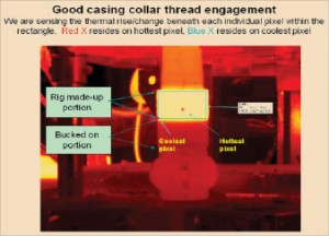
Figure 1 shows an example of a good makeup of a casing connection with a “bucked-on” collar, as viewed from the perspective of STV technicians. Notice the uniformity of color (representing temperature) throughout the box outlined in blue; this is the connection that is being made up. Below this area is the portion of the connection that was “bucked on,” that is, assembled in the factory beforehand.

Notice that the bucked-on portion does not appear to have a temperature appreciably different from that of its surroundings – this is because that portion of the connection is not moving, so friction is generating no heat. This is how a good casing connection should look. The friction should be applied nearly evenly throughout with the most intense engagement in the main body threads, and no motion at all in the bucked-on connection just below.
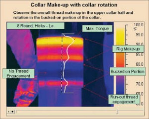
Figure 2, by contrast, shows a similar connection with collar rotation. Notice that the temperature in the top half of the collar (that is, the part being made up) shows nothing close to the uniformity of the connection in Figure 1. Worse, the highest temperatures are in precisely the wrong part of the connection – the edges – when the friction really should be greatest in the main body threads.
Worse still, there is a visible band of increased temperature below the connection being made up, in the bucked-on portion. This is not supposed to happen. Rig operators rely on the bucked-on connections to be correct and stable because they are performed under the supervision of the manufacturers.
Notice, too, that the friction in the bucked-on portion is localized in a relatively narrow band in the lower (outermost) part of the connection. This area contains “run-out threads,” which are not designed to bear a large portion of the connection’s torque – ideally there should be no friction or weight on these threads at all. The fact that this is the part heating up when the rig makeup portion is being connected suggests that most, if not all, of the torque applied in the bucking-on of the collar was opposed by friction in the run-out threads, which could cause structural problems.

Because the run-out threads are not designed to hold a lot of weight, there is a significant risk that the connection in Figure 2 may separate if it were sent downhole, potentially causing leaks.
Galling detection
Figure 3 shows how the system detects galling of certain threads. Galling occurs when an extreme amount of friction is applied to the material. In this case, nearly all the torque being applied to the connection is being opposed by friction in two mismatched threads, causing potentially serious structural damage.
The local concentration of the whole connection’s portion of friction to a few narrow bands also prevents the proper engagement of the rest of the threads.
Perhaps most alarmingly, this connection could appear completely normal to an operator examining its torque-turn graph, as the whole connection taken together applies about the same amount of friction (and consequently torque) as a proper connection would. The distribution of that friction is the problem.
Shoulder refurbishing
One of the DEA project tests involved a tool joint connection from which, according to the manufacturer, 1/32-in. of material could be removed at the shoulder up to three times for maintenance. For the STV system test, Global Systems had 1/32 in., 1/16 in., and 3/32 in. removed from identical brand-new connections.

This is an underestimate of the amount of material that would be taken off in a real-life situation: The company normally shaves both the pin and the box shoulder areas, and real-life wear and tear would erode the shoulders further.
Regardless, the STV system tests and Figures 4 through 7 show that the removal of material in this way actually significantly alters the way the connections make up.
Figure 4 shows a good makeup of this connection. Most of the friction is concentrated in the shoulder area, consistent with the manufacturer’s design. Observe a slight change of color immediately below the shoulder: This is the proper amount of thread engagement for this type of connection.
Figure 5 shows the same connection with 1/32 in. removed from the box shoulder. There are two higher-temperature zones instead of one at the shoulder and significantly less friction on the shoulder than in the brand-new connection. Most importantly, these two pictures are fundamentally different.
Figure 6, with 1/16 in. removed from the box shoulder, shows no shoulder engagement at all. If the two shoulders were touching, there would be some thermal reaction. This is completely inconsistent with the design of the connection.
Figure 7, in which 3/32 in. has been removed from the box shoulder, shows something similar: All friction is concentrated in the threads, and the shoulder is not engaging at all. In fact, a gap of .033 in. was measured between the pin and box shoulders after this makeup.
The assumption that 1/32 in. can be shaved off both the box and pin shoulders up to three times without changing the way the connection makes up cannot be correct. It remains to be seen how safe the connections in Figures 6 and 7 are; no studies have been done.
The industry has been assuming that, because the connections in Figures 6 and 7 generate the same torque-turn feedback as the one in Figure 5, the connections should be making up the same way. The STV system has shown that they are not.
Agreement with torque-turn
Figure 8 shows the torque-turn (converted to torque-time) graph from the connection in Figure 5 superimposed on a graph of maximum temperature vs time as measured by the STVS.

It takes less than a second for the temperature reading to respond to changes in torque, that heat lingers in the connection after the tongs have stopped applying torque, and that the slope of the temperature graph closely approximates the slope of the torque graph when the dimensions are corrected to match the maximum values.
In fact, the relationship between the two quantities is more complicated, but the small scale of the example allows the assumption that the two are linearly related to yield a close approximation.
Ovality detection
STVS premium connection images also can show ovality in the pin or box. In Figure 9, all the friction is in the run-out threads and the seal. More importantly, friction is not being applied evenly on the main body threads. The pin and box are both supposed to have circular cross sections on planes perpendicular to their axes, so the connection should heat up evenly along circular bands.
Here, however, either the pin or box is not perfectly circular, resulting in uneven friction and irregular temperature regions. Ovality like this can cause serious connection problems.
Soft seals
Tests have also shown that the STVS can detect and evaluate the engagement of soft seals. Operators would be able to detect problems before those connections are deployed. Images to illustrate this can be found in the online version of this article at www.DrillingContractor
.org.
TECHNOLOGY GAPS
The STVS is currently functional; however, a database needs to be compiled of manufacturer-approved examples of each connection making up properly so that engineers and technicians can see with greater certainty which connections make up acceptably.

This can be accomplished by the operator requesting an approved thermal signature from the manufacturer before tubular shipment to the location. Research needs to be done about how safe connections are at different levels of thread engagement. Several examples of connections that are clearly very good or very bad have been illustrated in this article; however, there are also cases in-between where determining the acceptability of a connection may be difficult.
A more comprehensive understanding of the risks and costs involved with different types of connection would allow operators and regulators to make more informed decisions.
SUMMARY
With the STVS, operators will be able to verify the engagement of individual parts of a connection, giving them a more accurate representation of the mechanical integrity of the connection as a whole. Global Systems has demonstrated that engineers and technicians using the system can identify collar rotation, misapplied torque, soft seal failure, ovality, excessive shoulder removal, galling, lack of engagement in any part of the connection, and other similar problems.
This ability will enable the identification of potentially problematic connections before deploying them, averting downhole leaks, parting, accidents and environmental problems.


This an excellent tecnology!! congratulations
I would like to get in touch with the companies which can provide this services, I can intoduce this tecnology in Brazil oil & gas Market.
Regards
Antonio caruso
cel 55 21 9804 2755