Dynamic load expansion bench takes new approach to expandable connections testing
By Richard DeLange, Ghazi Hashem, Weatherford International Ltd
Since the industry started installing solid wall expandable liners more than a decade ago, deployment systems have advanced more rapidly than expandable connection technology. Because conventional premium connection designs with metal seals could not withstand the distortion that occurs during the expansion process, the search immediately began for unconventional solutions, with the focus on pressure-sealing integrity before, during and after expansion.
Now, more than 10 years later, there are connection designs that can withstand the expansion process. Yet there is still no connection design that offers after-expansion performance equal to standard premium connections. Why?
A major obstacle, Weatherford International believes, is the industry’s inability to make prototype test samples that accurately represent connections that are expanded downhole. To that end, the company has created the dynamic load expansion bench, which can expand solid wall tubular connections with any combination of load and application conditions. By enabling accurate expandable connection testing, this could be a key step toward developing a connection design with advanced after-expansion performance.
LAB TESTING
Evaluation and qualification of new or existing connection designs have traditionally required physical testing even though finite element analysis (FEA) has advanced to the point that computer simulations of threaded connection performance are quite accurate. But most manufacturers and users still require and depend on physical testing to be sure the product works properly.
Test lab capability and standardized test procedures have been adequate for evaluating and qualifying threaded connections for normal tubing and casing applications. It is the additional step of expanding the test connections so that they accurately represent the connections expanded downhole that is perhaps the major reason there is no expandable connection design with high performance dependability.
Numerous testing procedures have been developed and standardized by API and ISO in the last 40 years. During the 1970s, API’s RP-37 focused on internal pressure integrity and thermal cycling of test samples. During the 1980s, API adopted the RP-5C5 format focusing on combined load testing and testing for varying levels of severity and risk. During the late 1990s, ISO and API adopted 13679, which fully expanded the amount of tri-axial combined load testing.
Compared with past recommended procedures, 13679 requires more control of the connection’s variables to ensure results effectively represent the design’s full range of performance capabilities. The dimensional tolerances for the pressure seals and threads are controlled to maximum and minimum combinations, then matched to the created test samples that represent the full range of dimensional possibilities for the seals.
The actual material properties are also factored into the testing to ensure that the connection’s capabilities are established for the tested material’s entire range of yield strength. The result of controlling these variables makes test-sample fabrication more difficult and expensive, but the credibility and completeness of the results are enhanced.
TESTING EXPANDABLE CONNECTIONS
The requirements established in 13679 for controlling the material and threading the test connections are adequate for expandable connections, and the test procedures can be used for testing expandable connections. But there are no requirements in 13679 for controlling the expansion of test samples before testing starts. Furthermore, it is an important fact that most or all expandable liner failures have occurred during the expansion process – proof that surface expansions must be accurate simulations of all downhole conditions, or weaknesses in the connections could go undetected.
An API resource group has been working on an annex to 13679 (API RP-5EX) that would set out a matrix of requirements for expanding and testing expandable connection test samples. The resource group working on this draft expects to distribute it sometime this summer to its members for technical comments.
For example, more pressure cycling than what is required in 13679 could be added to better simulate downhole expansion applications. When using pressure to drive the expansion cone, the rig must stop pumping each time a stand of work string or drill pipe has to be stood back. A 2,000-ft liner could have 70 pressure cycles before the expansion cone reaches the top of the liner, many more than required by 13679.
One foundation of 13679 is the requirement that the test connections be accurate representations of the connections that would be used downhole. That premise must be applied to building and testing samples of expandable connections; otherwise there would be no certainty that the threaded connections will withstand the expansion process and work properly in all well applications.
To add further complication, there are many variables in downhole expansion.
Up to now, it has been impossible to have expanding test connections in a laboratory environment that can include and control all possible downhole variables. Methods to produce test samples include only some of the possible conditions. The most common method has been to lay an assembly of test samples on the ground and pump a cone through it. Then the expanded connections are cut out and tested. While this method might accurately simulate expanding a horizontal liner that is not stuck, it is not adequate for other scenarios. For instance, it does not provide the ability to add and maintain pre-loads and load changes as the cone passes through the connection that are present in vertical applications.
The variables associated with expanding connection downhole fall mostly into two groups: those that must simply be incorporated into the process of expanding test samples and those that may vary enough to require their own test samples. At a minimum, the impact on performance from each condition needs to be understood.
THE VARIABLES
The first step to ensure the test samples are accurately expanded before testing is to use the same pipe and expansion system that would be used downhole. If there are to be two expansion systems for a connection design, both need to be evaluated to ensure the connection performance is proper. For instance, the expansion force can be applied mechanically using the rig or a downhole jack, or the expansion force can be applied by using pressure to move the cone.
The second group of variables is where the challenge lies. If expandable connections can be used in a liner that is short or long, stuck or free, suspended or on bottom, vertical or horizontal or in a deviation, and comes in different sizes, the connection designs need to be evaluated under all of those conditions. Moreover, if the connection’s load conditions before, during and after expansion are different along the entire length of the string, examples from at least some of those different locations must be evaluated.
While the number of samples required to accomplish all of these investigations is a challenge, the biggest challenge was that many of these condition variables could not be simulated in a lab environment.
The expansion system
Although these parameters typically do not vary, they still need to be incorporated in the testing. If they do vary, the impact to the connection performance needs to be understood.
• ID coating.
• Outside protective sleeve.
• Orientation of the connection with respect to cone travel (pin up or pin down).
• Cone speed.
• Pipe properties.
• Well fluid.
Application variables
These parameters typically do vary, so the effects must be evaluated and understood.
• Temperature.
• Bending.
• Expansion force cycles.
• Cone sizes (maximum, minimum and unexpanded conditions).
• Pipe/connection OD and wall thickness.
Major variables
These variables can combine to create varying load conditions for each connection in a single expandable liner, and the amount of variation is normally a function of the string length. Therefore, test samples need to be representative of connections from various locations in the longest string considered.
• Amount and type of expansion force (mechanical or pressure).
• String length.
• Hole angle.
• Bending.
• Connection location in the string.
• Constraint.
More importantly, the load on each connection before, during and after the cone passes through will be different. It is this phenomenon that had made laboratory sample expansion essentially impossible.
How the liner is constrained can have a meaningful effect on the expansion force requirement and on the distortion in the connection. The liner can be held in tension or compression, or both (so-called fixed-fixed expansion) could occur in a single liner. The fixed-fixed expansion, generally considered to exist when a string is stuck during expansion, can generate much higher tension loads and load changes during expansion.
AN EXAMPLE
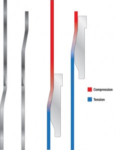
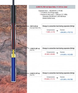
The expansion force along the entire length of a 2,500-ft, 11 ¾-in., 71 lb-ft vertical liner is 400,000 lbs. The internal expansion pressure is 1,890 psi, which generates 225,000 lbs along the entire length of the string below the cone due to the end thrust generated on the expanded ID at the bottom. If the string weighs 175,000 lbs, that entire load is on the cone and work string from start to finish because the string is not on bottom. The load that varies is each connection’s load before the cone reaches it and after the cone has expanded it.
Consider the connection in the middle of the liner at 1,250 ft from bottom. The compression on that connection from the weight of the pipe above it is -87,500 lbs. Once the cone expands the connection, it will have a tension load equal to the pipe weight below it (+87,500 lbs), plus the end thrust from the expansion pressure (+225,000 lbs), which equals +312,500 lbs. Behind the cone is +312,500 lbs, and in front of the cone is -87,500 lbs compression, which, when added, equals the expansion force of 400,000 lbs.
At 100 ft from the top of the liner, the compression in front of the cone is only -7,000 lbs while the tension behind the cone is 168,000 lbs of string weight and 225,000 lbs of end thrust. Again, the sum of the loads on the cone and work string equals the expansion force of 400,000 lbs.
A 2,500-ft, open-hole liner will have at least 60 threaded connections, each with a different load change as it gets expanded. In a normal, unexpanded casing string, the size and length of the string determines the weight or load on each connection. But these loads are all below the yield strength of the connection, so testing is simply a matter of applying a load to the connection equal to its rating.
With expandable connections, the load changes as the connection is getting stretched beyond its elastic limit. That means a meaningful number of those pre-loads and load changes on the tested connection have to be evaluated to ensure there are no differences in the way the connection works after expansion.
At least the top-, middle- and bottom-load conditions should be tested to ensure the connection functions properly when used in a fairly long expanded liner.
There are many test frames capable of performing 13679-type tests on expanded connections. The challenge is to build test samples that accurately represent the actual product. So-called driveway expansions do not allow incorporation of many of the most important variables.
ADVANCED CONNECTION DESIGN
When Weatherford analyzed why an advanced threaded connection design had not been developed, the most glaring problem was the inability to make prototype test samples that accurately represented connections that had been expanded downhole. Because the load dynamics can vary significantly in different application scenarios, the ability to make test samples under all of the possible conditions would be needed before expandable connection technology could be advanced.
Expanding connections downhole and then retrieving them is not a viable approach, so an expansion bench would be needed that could simulate virtually all of them. This dynamic load expansion bench was designed for one purpose – to expand solid wall tubular connections with any combination of load and application conditions. “Load dynamics” describes the mechanical loads on a connection before it is expanded, the dynamic change in load as the expansion cone passes through the connection, and the total load on the connection after the cone has completed the expansion.
The expansion forces and dramatic load changes, which occur over just a few seconds as the cone passes through the connection, combine to create the dimensional changes. To achieve advanced connection performance, the new connection design has to withstand the entire range of load changes.
As mentioned, it’s inadequate to have test samples expanded in an assembly laid on the ground and have an expansion cone pumped through it. To achieve a proper expansion simulation in a laboratory environment, a bench is needed that could apply and maintain all of the pre-loads on the test assembly while the cone is moved through the sample.
The three broadest types of pipe expansion are:
• Mechanical: pulling the cone through the pipe with the twin long cylinders applying the total expansion force.
• Dynamic load: applying a compression load, a tension load, then pressure to generate the total expansion force.
• Fixed/fixed: mechanical or variable load expansion, except both ends of the pipe are constrained so that length shrinkage is impossible.
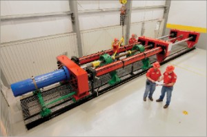
The bench has three crossheads, three hydraulic cylinders, a high-pressure water source, and the ability to maintain different pre-loads in the assembly while the expansion cone is moving. Every working part of the machine is computer-controlled so that all three types of expansion can be done.
The two long cylinders (the compression cylinders) are connected to the moving crosshead, which is connected to the cone with the cone rod. These cylinders each have a 15-ft stroke. The tension cylinder is connected to the tension crosshead and is used to apply tension to the work piece and adjust for length change during the expansion process. It can also be locked to simulate a fixed-fixed expansion.
The center crosshead is fixed to the frame. There are load cells at the ends of both long cylinder rods and between the long cylinders and the tension crosshead.
The controls monitor all of the cylinder pressures and cylinder rod positions and use this data to control and run the bench. The work piece can be as large as 13 3/8 in. before expansion or as small as 3 ½ in. The maximum force that can be generated by the two compression cylinders or the tension cylinder is 650,000 lbs, which is adequate to expand any pipe size within this range. The triplex water pump system can generate more than 5,000 psi. The cone speed can be controlled between 2 to 10 ft/min.
Mechanical load expansion
This is the easiest of the expansions. The cone assembly and cone rod is pre-installed in the work piece; then an end cap is welded to that end. The other end of the cone rod is attached to the moving crosshead. Finally, the long cylinders push the moving crosshead until the expansion is completed. The bench can perform this expansion constraining the assembly in tension or compression.
Dynamic load expansion
This is the most complex and is the scenario that could not be simulated in a lab before. The cone will get force from all three systems:
1. The long cylinders will push on the moving crosshead, which pulls on the cone. This applies a compression load to the work piece between the cone and the center crosshead that simulates the string weight above the cone as it moves up the string in a vertical liner. The amount of compression depends on where the connections are in the string. The higher up, the less weight or compression. At the bottom, the unexpanded connections above the cone are experiencing the weight of the string above so the compression load is much higher.
2. Next, the tension cylinder will pull on the work piece, applying a tension load to the pipe behind the cone. Again, the amount of the tension depends on how much pipe would be hanging from the connections after expansion.
3. Finally, internal pressure is applied to the cone assembly until the cone begins to move. The compression, tension and pressure combine to generate the expansion force required to start the cone up the string. The pressure generates an additional tension load to the work piece behind the cone from the end thrust.
At that point, the controls maintain the pre-loads while allowing the cone to move. The compression cylinders extend at exactly the speed of the cone so that the compression load in front of the cone is maintained. The tension cylinder also extends to compensate for the work piece shrinkage while it is pulling on the assembly to maintain the tension pre-load.
Fixed-fixed expansion
When a liner is stuck or when the ends are constrained, the expansion is said to be a fixed-fixed expansion. This scenario will generate an additional tension load because the work piece cannot shrink in length. The bench can simulate this by simply locking the tension cylinder after the preloads are established. The cone is then pumped through the assembly.
Expansion inside a deviation
Another application scenario is expanding a liner that is inside a wellbore deviation. This scenario creates additional tension on one side of the bent string before expansion and compression on the other side. If it is stuck, the samples must be bent before expansion, then constrained at both ends to properly simulate all of the loading or forces.
There have been some threaded connections expanded while laying on the ground with the work piece forced into a curve to simulate a wellbore deviation. The forced curve was created by posts fixed into the ground. Because the curve was not fully supported, some test connections may buckle, which is not an accurate simulation. To solve this problem and to get dependable data, Weatherford designed a constant-radius bending frame.
Because casing strings inside a wellbore deviation can be stuck, the frame is designed to be used in a traditional load frame so that the expansion can be done with fully supported bending and a fixed-fixed constraint. Because the radius support is continuous, there is no tendency to buckle the connection, which allows a more accurate evaluation of the expanded test sample when it is tested.
The dynamic load expansion bench and the constant-radius bending frame are located in Weatherford’s R&D lab in Huntsville, Texas. All preparations needed before testing expanded connections can be done here.
The lab also houses a coordinate-measuring machine, load frame, power tongs, cone assembly insertion system, welding station and other equipment, all computerized and monitored using data acquisition systems. The threading of new connection concepts is done at the same facility on a threading line built for prototyping expandable connections.
Click below for an exclusive interview detailing reliable expandable connections.
[youtube C48xIWYJuGg]Read the full article on this video here.


