Field tests show aluminum drill pipe can extend operating envelope for extended-reach drilling
By Mark Jenkins, Alejandro Castro Rodriguez, Christian Linke, Georg Mader, Baker Hughes; Mark J Davies, Alcoa Oil and Gas
One challenge for the industry is how to extend the limits of rig capacities without significantly increasing cost. A way to address this challenge is to use a lighter drillstring.
The objective of this investigation was to determine whether, by reducing string weight and changing the material properties of the drillstring, it is possible to extend the operational envelope of the drilling rig without having a detrimental impact on the drilling process. A field-testing program was carried out on a full-scale experimental drilling rig in Oklahoma. Steel drill pipe (SDP) was exchanged for aluminum drill pipe (ADP) to greatly reduce the weight of the drillstring without significantly reducing its mechanical integrity.
Two representative geological sections on separate wells were drilled with a string containing ADP, and extensive surface and downhole data sets were obtained. Dynamic drilling data were recorded at three discrete points along the drillstring. At two of these points, mechanical drilling data was collected.
An advanced modeling package was used during the planning phase of these wells and during the post-drilling analysis of the data sets. Through interpretation of the results from the testing program and by extensive modeling, it was possible to extrapolate the extent to which the operating envelope may be extended. These models were then used to challenge extended-reach drilling (ERD) profiles and investigate if the drilling envelope could be extended by applying ADP to future projects.
ERD
ERD operations are gaining momentum because they allow the exploitation of reserves that were previously uneconomical to produce. By increasing the lateral departure from the production site to the reservoir and by drilling horizontally through the reservoir, several projects now fall within an economical span.
Nevertheless, there are constraints inherent to these operations:
• An increased amount of tubulars are required to reach the potential pay zones.
• High tensile axial loads are experienced by the tubulars near the surface and high compressive loads on the tubulars in the bottom of the hole.
• Torque and drag increasing as a result of elevated loads created by the drillstring running and rotating.
• Cyclic bending stresses can diminish the fatigue life of the drilling components.
• Hole-cleaning issues at increased inclinations.
Drillstring reliability is critical for the success of such ventures, especially when these operations are performed on expensive rigs.
The loads experienced by the drillstring can be in the form of tension, compression, bending, torque and pressure. In ERD operations, the weight of the tubulars determines the rig selection in terms of handling capacity. The rating of the drilling line, crown and traveling block must also be selected based on this factor. The dynamic loads during drilling (such as high compression on the rig legs caused by the hook load) must also be taken into account. Other loads include torque and drag, and they can be high enough to raise concerns about the possibility to reach other targets later in the field development with current rig capabilities.
When analyzing DP, a critical parameter that restricts its movement is its own weight. While these tubulars are inside the wellbore, their weight can create frictional forces due to contact with the borehole wall and preinstalled casing strings. Therefore, efforts toward reducing the tubular weight must be considered. Using lighter materials has proven to be a good alternative for weight reduction. It also allows for bigger pipe diameters, which can reduce pressure losses and therefore provide more hydraulic power for the bottomhole assembly (BHA) and bit.
This study focused on ADP as a real substitute for conventional SDP.
Some reservoirs located within a few kilometers from shore can now be reached without the use of offshore installations. In addition, projects can be completed in environmentally sensitive areas by drilling several wells from the same location. However, there are several problems, as discussed below.
Torque and drag
The frictional force between the pipe and the borehole/casing wall is the most important factor in determining the torque and drag behavior of the tubulars. The most common sources of torque are the bit torque; the torque along the wellbore; and the mechanical torque (cuttings, stabilizers, centralizers).
Meanwhile, the drag accumulates mainly during picking up, slacking off and slide drilling. Hole inclination and curvature will bring the drag forces to higher levels due to the gravity, and the compressive forces that push the string against the low side of the hole and due to the tensile forces that pull the string to the high side.
Torque can increase significantly as a result of increasing compressive loads. Therefore, buckling behavior is important when analyzing torque requirements. For long horizontal or high-angle sections, sometimes slide drilling is required for extended periods of time. Excessive drag can limit weight transferred to the bit, enhance drillstring buckling and reduce directional control. High levels of torque can exceed the capacity of the top drive, rotary tables or the drillstring itself.
High levels of drag can go beyond the hoisting capacity of the rig or the tensile limits of the tubulars. Rig capacity and drillstring upgrades may be necessary in order to reach the targets.
Bending
Shallow kick-off points (KOP), short/medium-radius curves and high dogleg severity (DLS) are common in ERD wells. In such spots, the pipe could be rotated under high tensile or compressive stresses. Initial bending occurs in the curved sections, but the axial compressive load pushes further bending between the tools joints. Under such conditions, the tubulars can experience failures in the form of yield and fatigue due to the high bending loads.
Typically, maximum bending stress is experienced in the middle of the DP body. However, once the pipe body contacts the wellbore, the location of the maximum bending stress tends to move away from the middle of the pipe body as the compressive load is increased. This is because the pipe cannot bend anymore due to the supporting action of the borehole wall, which results in further deflection in the non-contacting portion of the DP.
Fatigue
Fatigue is a form of failure experienced by a material at cyclic loading stresses much lower than its tensile/yield strength. The fatigue behavior is usually described by plotting the stress amplitude (S) against the number of cycles (N) to failure in a so-called S-N curve. The performance of a material is characterized by the endurance limit at N cycles.
In the case of drilling operations, cyclic bending stresses are experienced by the DP when it bends as it rotates. If the magnitude of these stresses is high enough, fatigue stressing occurs at every revolution and accumulates through the service life of the tubular. Fatigue failures are usually a result of rotation of pipe in high doglegs (DLs).
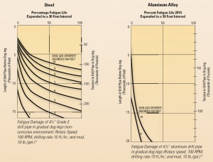
Long, gradual DLs are supposed to have a bigger impact on fatigue life because the pipe is rotated while experiencing high bending stresses for longer periods of time. Figure 1 illustrates the reduction in fatigue life experienced by ADP and SDP, respectively, while going through gradual DLs. The graphs show that ADP can pass through more severe DLs without damage.
However, DLs are not the only factor that determine fatigue behavior. The side forces exerted by the tool joints and body of the pipes against the borehole walls also have influence. Nevertheless, since ADP is lighter, the side forces are expected to be considerably smaller than SDP.
Furthermore, the graphs were prepared considering a mud weight of 1.2 kg/l (10 ppg). In a heavier fluid, the tension and bending stresses would be smaller due to the buoyancy effect, which is considerably higher for ADP than for SDP. From the graphs, it is also clear that the DLS, which a tubular can withstand, decreases with an increase in tension.
Buckling
As the angle increases in the wellbore, so does the tendency for the pipe to lie down on the lower side of the hole. This allows the pipe to reach a state of stability and to carry higher axial compressive stresses without buckling. However, when more energy is put into the system, buckling can occur. Depending on the magnitude of the compressive loads and the stiffness of the tubulars, sinusoidal or helical buckling can develop. A further increase in the compressive load will lead to lock-up, where the side forces are extremely high and no more weight can be transferred from one point to another.
Dawson and Paslay (1982) compared the buckling behavior between ADP and SDP in inclined holes. It was proven that the hole supports the pipe along its length and provides it with more resistance to buckling. They established the boundaries between regions of stable and unstable behavior. For DP in compression, their analysis provided the maximum compressive loads that the pipe can withstand without experiencing buckling. ADP presented a higher tendency toward buckling than the SDP. Lower stiffness and modulus of elasticity of ADP explain this behavior.
Casing wear
Casing wear is mostly caused by friction between DP tool joints and the inner surface of the casing during drillstring rotation and tripping. A key contributor to casing wear is DLs, especially at shallow depths, where the drillstring’s high tension forces generate high lateral loads. According to Benotmane et al (2008), the elements that determine the casing wear rate are:
• Side forces.
• Wear factor (determined by tool joint materials and drilling fluid properties).
• Contact distance between the tool joint and the casing.
• RPM (directly proportional to casing wear).
• ROP (casing wear rate is inversely proportional to ROP).
Casing wear is most likely to occur in ERD wells in unexpected DLs near the surface, and in highly deviated wells with a low ROP. Casing wear can lead to a reduction of the burst and collapse resistance of the tube, which can lead to high repair costs or even well abandonment.

ALUMINUM DRILL PIPE
ADP is a seamless tubular with heated, screwed-on steel tool joints or integral aluminum tool joints. The key requirements for the design of ADP are specified in ISO-15546, “Aluminum Alloy Drill Pipes for the Oil and Gas Industry.” The norm establishes that ADP should be handled in the same way as SDP on the rig, so it makes sense to use steel tool joints. The extension of service life for API connections is also better than its aluminum counterpart.
Furthermore, the service life of steel threads with aluminum bodies is longer, as the singles of ADP weigh significantly less than their steel equivalent, which, in turn, reduces wear of the connection at every make-up. Experience with mixed strings (ADP and SDP) has highlighted the need to use conventional steel tool joints to avoid loss of time and effort in changing elevators on the rig floor.
The tool joints for ADP are a super-shrink grip type. The pipe is machined with six modified ACME threads/in. (RH) on a 3/8-in. taper/ft. The end of the pipe is provided with a smooth concentric shoulder. Beyond this point, the pipe is tapered through the transition zone.
The inside of the pipe end of the tool joint displays the threads, the end shoulder and the counterbore. The annular section of the tool joint, which is heated to approximately 700°F to 750°F before it is screwed on, contracts after assembly and provides an additional interference fit. Once assembled, the pipe and tool joint are quenched by water. The pipe end is thus firmly gripped by the tool joint at multiple points, providing a pressure-tight assembly and efficient transfer of tension, torsion, bending and compression loads between the pipe and working connection.
FIELD TEST
To investigate the performance of ADP in a drilling environment, a series of experiments were carried out at a test facility located in a depleted oilfield where the geology is well documented. All rocks encountered here are consolidated and cemented sedimentary rocks of both marine and nonmarine origin. Shale is the predominant rock type, constituting more than 70% of the rock section above 2,400 ft (731.5 m).
Sandstone and siltstone comprise most of the remaining rock at shallower depths. Below 2,400 ft, limestone, sandstone, shale and dolomite were encountered in approximately equal proportions. Numerous thin coal beds and minor oil shows were encountered.
The rig itself is a free-standing derrick and hoisting system rated to 1.2 million lb hook load. Other major components of this facility include the Canrig 500-ton, 1,250-hp, AC-driven top drive capable of 256 RPM at 23,700 ft-lbs continuous torque. There are two Skytop Brewster B-1300-T triplex pumps; Tandem Cagle shale shakers; 40 and 140 mesh screens, Brandt EPI mud cleaner; and a Bird model 2500 centrifuge.
ADP was used to drill 799.5 ft (243.7 m) in 27.49 drilling hours and accumulated 63.33 circulating hours. The tests were run while drilling wells ADP1 (using 15 singles of alloy 2014 ADP) and SDP1 (steel).
The well paths had similar profiles, with a slight deviation from vertical (up to 30°) in the depth of interest. For this study, only the interval from 1,350 to 1,750 ft of TVD (411.5 m to 533.4 m) was covered.
The testing was performed while using two drilling mechanics and dynamics diagnostic MWD tools in the BHA. In combination with the surface drilling measurements, it was possible to review the dynamic behavior of the ADP compared with a conventional drillstring. In addition, the sensor tools monitored various mechanical parameters, such as downhole weight on bit (WOB), downhole torque (TOB) and bending moments.
This tool simultaneously takes 14 measurements, with each sensor channel sampling data at a rate of 1000 Hz and further analyzes the occasion and severity of various dynamic drilling phenomena, such as lateral and axial vibrations, whirl and stick-slip.
An 8 ½-in. PDC bit, 6 ¾-in. BHA, 9 ½-in. hole opener, 5-in. heavy-weight drill pipe (HWDP) and 5-in. DP were used to drill both wells with water-based mud. In both cases, two sensor tools were located in the BHA: one near the bit and one above the hole-opening device. Therefore, the measurements of WOB, TOB, RPM, bending moment and the diagnostics of drilling dysfunctions were taken at BHA depth, which does not reflect completely the behavior of the DP.
Fifteen singles of ADP were made available for the tests, comprising just 25% of the 1,750 ft (533.4 m) of drillstring; therefore, results were inconsistent when looking for differences in performance between ADP and SDP.
RESULTS
Weight: The total weight of the drillstring was not drastically impacted by the use of ADP instead of SDP. The theoretical buoyed weight (in 10 ppg / 1.2 kg/l mud) of the ADP was about 47% of its SDP counterpart. However, only 15 singles of ADP (about 450 ft / 137 m) were employed in the runs. This caused a difference in total weight of 22%.
Torque and drag: Some differences in terms of torque and drag were detected. There was a reduction of 36% in torque and 50% in drag by using ADP. By using a lighter material, the normal force exerted by the tubulars on the borehole walls was reduced. This helped to decrease the torque and drag forces. This should be valid depending on the well inclination, i.e., in vertical wells an increase or decrease in the tubulars’ weight would not have any influence on the normal forces.
Drilling dynamics: The sensor tool provided results for the drilling and reaming scenario. Both scenarios delivered results that were deemed too inconsistent for the purposes of this study. While drilling, the biggest influences on the results were the bit-formation interaction and the configuration of the BHA. While reaming, the factors that determined the dynamic behavior were the DP characteristics and the operating practices. Figure 2 depicts the vibration severity levels from the lower sensor tool. Lateral, tangential and axial vibrations while drilling and reaming remained at low levels for both strings at both measuring points.
MODELING
A specialized software package was used to model different drilling scenarios while using ADP and SDP. It allowed simulating drilling conditions such as torque and drag, hydraulics, swab and surge, casing wear, BHA performance and vibration analysis. The software incorporates an entire tool catalogue for use in the simulation of any equipment, i.e., rotary steerable systems (RSS), downhole motors, MWD/LWD tools, reamers and stabilizers. Several materials can be modeled, including steel, aluminum, titanium, non-magnetic monel and composites.
The software does not accumulate the casing wear over multiple bit runs (wear rate was calculated only for single-bit run). For hydraulic calculations, the software considered the pipe to be concentric in the center line of the wellbore and did not consider pipe and wall roughness.
Torque, drag and hydraulic simulations were performed to evaluate the limitations of the rig’s rotary table/top drive, pumps and tubulars. The evaluation involved surface equipment capacities (maximum rotary torque, hoisting capacity and stand pipe pressure), limits of the drillstring in terms of torque, tension, compression and stresses; maximum buckling loads and available WOB while sliding/rotating.
The wellbore profile corresponded to an ERD sample. The well was completed with 18 5/8-in. (1,130-m MD), 13 3/8-in. (4,240-m MD), 9 5/8-in. (6,514-m MD) casing and a 7-in. liner (8,877-m MD). The simulations were performed in three phases:
1) Drilling to 8,877 m MD according to the original plan.
2) Drilling to 12,000-m MD to test the performance of the SDP and ADP as if the target were located at that depth.
3) Test the limits of displacement of the SDP and ADP string.
In all stages, the strength of the tubulars and the rig capacities were taken as the limiting factors.
RESULTS
First phase
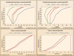
Figure 3 compares the expected loads along the drillstring under drilling, slacking off, picking up and rotation off-bottom scenarios for the SDP and ADP strings. A maximum tensile load of 1554.5 kN was experienced by the SDP, while the ADP was subjected to only 724.4 kN. The fatigue safety factor improved from 1.32 to 2.28 and the yield safety factor from 1.87 to 2.71. However, the sinusoidal buckling WOB was 10 times higher for SDP because of the higher stiffness of the steel compared with the “more elastic” aluminum.
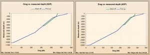
Figure 4 depicts the expected torque for both drillstrings. By using ADP, there was a significant decrease in the torque readings from 57.3 kN·m to 33.1 kN·m (42% reduction).
Other results showed that the ADP model reduced the buoyed weight of the string by 53% and the drag by 48%. The relative casing wear (observed at the KOP, due to the high local DL) was reduced from 6.8% to 3.3%.
Due to the elastic properties of ADP, it was thought to be more susceptible to stretching than SDP. On the other hand, an ADP string experienced less tensile loads because the mud density exerted higher buoyancy force, thus balancing this effect. The ADP stretch was measured at 5.63 m while picking up, which was very similar to the number from the SDP model (4.88 m).
The pressure losses increased in the ADP model due to the greater pipe wall thickness. Equivalent circulating density was higher for the ADP (2.46 kg/l) than the SDP model (2.11 kg/l) due to the reduced clearance between the DP and the wellbore.
The reductions in weight, torque and drag by the use of ADP could enable the use of drilling equipment with a lower rating to reach the target. While Rig 1 could be used for the ADP design (33.1 kN·m of torque and 2,689 kN of weight), the elevated handling and torque requirements for the SDP proposal (57.3 kN·m and 3700.1 kN) would require the use of Rig 3 (Table 1), which meant a higher rating rig.

Second phase
The proposal for this stage was to extend the measured depth (MD) to 12,000 m while keeping all other operating parameters unchanged. The only parameter modified was the flow rate (changed for both models from 2 to 1.80 cu m/min due to limitations in standpipe pressure).
Table 2 shows a summary of the results for the second phase.The first results from the SDP model (comprised 4,700 m of 5-in. and 5,382 m of 6 5/8-in. S-135 SDP) indicated that the torque required (89.1 kN) exceeded the capability of Rig 6 (70.5kN).

Further models proved that the maximum depth achievable with SDP was 10,200-m MD, under the given boundary conditions.
The results indicated that the torque and handling requirements were within the limits of Rig 2. The lower drag (Figure 5) of the ADP string would allow slide drilling to continue down to 9,400 m if it was required.
However, the pressures losses within the drillstring amounted to 38.57 MPa (5,594 psi), which was beyond SPP capabilities. The reduced inner diameter of the ADP accounted for the higher losses. Further modifications to the model by reducing the pumping rate did not show a big influence on the SPP reduction. Therefore, it was necessary to modify the design by including ADP with a bigger ID. The optimum model was composed of 2,500 m of 5.787-in. (147-mm) and 9,382 m of 6.614-in. (168-mm) ADP.
Even when the ADP model developed comparatively more buckling than the corresponding SDP, it was only a sinusoidal deflection without reaching into the helical region. This condition allowed drilling to continue in rotary mode. However, it was not possible to run-in-hole without rotation due to the high compressive loads.
Third phase
The goal of the third phase was to discover the theoretical displacement limits of the ADP and SDP. Rig 6 could deliver 70.5 kN·m of torque; however, the torsional limit of the conventional ADP (alloy 2014) was rated at 59.6 kN·m. If the required torque was beyond the capacity of the pipe, a high-strength alloy (79.5 kN·m) ADP was used with a 5 ½-in. FH connection (71.9 kN·m). Thus, the rig’s top drive was the limiting factor.
The limit for the SDP model was determined at 10,200-m MD in the second phase, so no further analysis was performed.
For the ADP model, the maximum drilling depth under the given operating parameters was found at 17,500 m. The torque required (70.04 kN·m) and handling capacity (503.2 tons) approached the limits of Rig 6. The proposed ADP-only model consisted of 8,000 m of 5.787-in. (147-mm) and 9,382 m of 6.614-in. (168-mm) ADP.
Additionally, the possibility of including SDP and ADP in the same drillstring was explored. With a maximum drilling depth of 17,500 m, this possibility was simulated in this study. The ADP-SDP model was created with 14,000 m of 5.945-in. (151-mm) OD and 4.921-in. (125-mm) ID ADP and 3,382 m of 6 5/8-in. (168.3-mm) OD and 5.965-in. (151.5-mm) ID S-135 SDP.
Similar levels of casing wear, buckling and torque were found in both models. The ADP-only model presented advantages in fatigue safety factor and the possibility to continue in slide-drilling mode for a further 800 m. On the other hand, the ADP-SDP model was more advantageous due to reductions in weight in air, drag, twist, stretching and pressure losses. Therefore, the choice of the most optimum model should be made depending on the factors that need to be improved for a given application.
OUTLOOK
Considerable advantages of ADP over SDP were observed during the simulations. Reduced levels of torque, drag, casing wear, fatigue, power consumption, and the possibility to use lower-rating rigs were some of the benefits.
Rig 1 (Table 1) was deemed capable of reaching the objectives of the first and second phases of the simulations when using ADP. In contrast, Rig 3 was necessary to reach the target in the first phase with SDP. The maximum drilling depth was found at 17,500-m MD for the ADP string while only 10,200-m MD was achievable with SDP under the given boundary conditions.
Most of the DP was run under compression in the models. The pipe showed little or no buckling tendency while rotary drilling was used, even at the maximum expected WOB. On the other hand, in potential motor applications or non-rotating drillstrings, sinusoidal or helical buckling developed along the DP and even in the HWDP. This was not desirable but could be tolerated, even though it impacted the weight transferred to the bit.
In some cases, the helical buckling increased significantly, leading to lock-up. A solution could be the use of HWDP (to add stiffness to the string), but a large quantity could be required, which would cause increases in torque and drag and mud-pressures losses. Controlling the WOB was another option; however, it could reduce the ROP to unacceptable levels. When slide drilling was not possible anymore, the use of a rotary steerable system seemed to be the best choice.
In the third phase, the ADP-only model showed a bigger tendency toward buckling; however, it only reached a sinusoidal state, allowing drilling to continue. Extreme buckling could cause contact of the body of the pipe with the borehole or casing wall, and its abrasion-type wearing susceptibility will lead to rapid erosion. Consequently, ADP should not be run in sections where high compressive loads are expected but under tension to maximize its benefits.
In cases where this is not feasible, a solution could be the use of wear pads or pipe with increased wall thickness.
In the last model run, SDP was located in the upper part of the string. The pipe near the surface typically experiences the highest tensile loads; therefore, the higher yield and tensile strength of the SDP are a definite advantage in this section.
DLs were the most susceptible areas for casing wear. The situation worsened when the DP in the DL was under high tensile stresses. High curvatures plus high tensile loads in the DP were identified as the main source of casing wear, regardless of the material used in the drillstring. Where possible, shallow KOP should be avoided. Catenary or pseudo-catenary profiles could help in these situations.
CONCLUSIONS
This paper focused its attention on one aspect that should be improved to accomplish the goals of ERD drilling: drillstring optimization. It was demonstrated that, by using ADP instead of SDP, several benefits could be obtained.
Despite the limitations during the tests, they provided evidence about the improvements that can be achieved by the use of a lighter material in the drillstring. Reduced levels of buoyed drillstring weight, torque, drag and bending moments were acknowledged. Drawbacks of ADP included:
• Higher buckling tendency.
• Susceptibility to corrosion with pH values in excess of 11.0 for prolonged periods.
• Higher price (50 to 150% higher).
• Lower yield/tensile strength.
However, its advantages can surpass the disadvantages:
• Equivalent derrick loads can be reduced, an opportunity to reach extended targets from the same locations and without expensive rig upgrades.
• Drillstring weight reduction and higher strength-to-weight ratio.
• Reduction in drillstring torque and drag.
• Tubulars with improved fatigue life.
• Maximum permissible DLs.
• Decrease of casing wear.
• Drillstring axial and bending stresses are less due to bigger buoyancy factor and smaller drag forces.
• Stretch under drillstring’s own weight is similar or smaller than that of SDP.
• Greater flexibility that allows increased build-angles for side tracking.
ADP is not a “one-size-fits-all” solution. In specific cases, its benefits can be outweighed by the disadvantages. The key lies in a case-by-case preplanning phase.
So far, utilization of ADP has been restricted to a few projects worldwide. Performance and availability of SDP in conventional projects has made it the top choice. However, the increasing tendency toward ERD and deep-drilling should open a window of opportunity for ADP.
Acknowledgements
The authors would like to thank the management of Baker Hughes and ALCOA Oil and Gas for the support and the
permission to publish this paper. Thanks are extended to all individuals who participated in recording and documenting the
field tests presented in this paper. Special thanks to Dudley Guillory for the great help at the test facility.
References
1. Robertson, N. BP Exploration and Production Technology: “BP’s Industry Drilling Envelope”. Update: June of 2009
2. Gelfgat, M. et al.: “Aluminium Alloy Tubulars for Oil and Gas Industry”, SPE 97035. Presented in Dallas, TX, USA, 2005
3, 5, 8. Benotmane, K. et al: “Advantage Engineering Manual (version 2.1)”. Baker Hughes Inteq. Celle. 2008
4, 7. Dawson, R. and Paslay, P.R.: “Drill pipe Buckling in Inclined Holes”. SPE 11167. Presented in New Orleans, LA, USA.
1982
6, 14. Hansford, J.E. and Lubinski, A.: “Cumulative Fatigue Damage of Drill pipe in Dog-Legs”. Journal of Petroleum
Technology. 1966. Pages 360-362
9. Sinor, A. Et al.: “Unique Field Research Facility Designed to Accelerate New Technology Development and Enhance Tool
Reliability”. Paper AADE 01-NC-HO-36, presented at AADE Conference, Houston, Texas. 2001
10. Heisig, G. et al.: “Downhole Diagnosis of Drilling Dynamics Data Provides New Level Drilling Process Control to
Driller”. SPE 49206. Presented in New Orleans, LA, USA. 1998
11. Chandler, R. et al.: “Advanced and emerging drill string technologies overcome operational challenges”. World Oil
Magazine. October 2006 issue, page 26
12, 13. ALCOA Oil and Gas: “Drill pipe Engineering Data. Version 1.0”
15. ISO 10407: “Petroleum and natural gas industries- Drilling and production equipment – Part 1: Drill stem design and
operating limits”. 2004
IADC/SPE 128910, “Can Aluminum Drill Pipe Extend the Operating Envelope for ERD Projects?” was prepared for presentation at the 2010 IADC/SPE Drilling Conference & Exhibition, 2-4 February, New Orleans, La.
Additional graphics & tables


