Concepts, misconceptions about kick tolerance
By Helio Santos, Erdem Catak and Sandeep Valluri, Safekick

Even though kick tolerance is a critical and fundamental concept for the drilling industry, no standard is used by all operators and drilling contractors. Additionally, the concept is not widely employed or understood to help essential decision-making during drilling. This often leads to discussion during drilling of whether it is safe to continue drilling. As wells are drilled in more challenging environments, it takes only a small variation in kick tolerance calculations to lead to a premature abandonment of the well if a more conservative approach is used or, in other cases, to be against safety when the kick tolerance calculated is higher than what it should be.
To develop a more accurate kick tolerance tool, which would include important effects that are usually not considered in today’s calculations, a review of the state-of-the-art has been carried out. This review showed that what is recommended and in practice in the vast majority of cases is a very simplified and conservative calculation, not taking advantage of even simple spreadsheets to include some important effects.

Misconceptions on how kick tolerance is calculated were identified. Even though some of them have a small effect on the final result, it is important to have a solid and correct foundation to build on, as the intention is to incorporate other important effects to the final tool. The ultimate goal is to have a tool that can be used by engineers at the office during the well-planning stage, as well as on the rig, to allow a simple and direct evaluation of the safety condition to better define the continuation of operations.
A simplified approach has traditionally employed a single bubble model, and this allows the calculations to be done without any computer help. Although computer power is not a problem and multiphase flow models are available to reproduce gas behavior inside the wellbore, the examples shown here will use the same simplified model the industry has employed for decades, i.e., assuming a single bubble and constant temperature, while ignoring the effects of gas solubility, dispersion and migration.

The objective is to highlight the misconceptions with a direct comparison, reducing the variables to a minimum.
KICK VOLUME
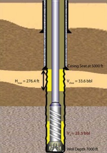
The first problem identified in the current industry-recommended kick tolerance practice is related to the calculation of kick volume on bottom. The first step is to define the maximum vertical kick height (Hmax) at the casing shoe, assumed to be the weakest point in the open hole, based on fracture gradient, mud weight, kick fluid density and predicted pore pressure. The second step is to calculate the kick volume at the casing shoe, Vshoe, from Hmax, and then take the volume to bottom (V1) using Boyle’s Law (Figure 1).

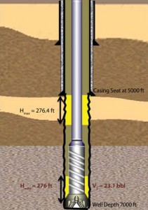
The third step, and where the problem lies, is to calculate the kick volume at bottom around the BHA, V2, and assume as the kick tolerance the smaller of the two volumes between V1 and V2. The same Hmax is used for calculating V2, assumed to be at the bottom of the well (Figure 2).
What is conceptually wrong here is that, if the BHA length is greater than Hmax the kick cannot be circulated out of the wellbore as it will reach the top of the drill collars with a kick height greater than Hmax, which would induce losses at the shoe.
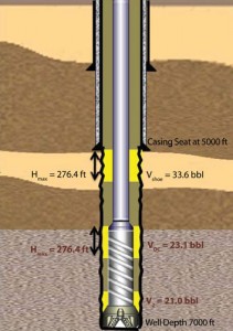
To properly address this point, an extra calculation needs to be done if the BHA length is greater than Hmax. Instead of having Hmax at bottom and calculating V2, Hmax must be located at the top of the drill collars, calculate the volume across the top of drill collars, VDC, and then take this volume to the bottom of the wellbore using Boyle’s Law (V2), in the same way it is done with the kick volume calculated at the casing shoe (Figure 3).
Then select the smaller between V1 and V2 as the kick tolerance. If Hmax is greater than the BHA length, the difference in annular volume most of the time compensates the expansion of the gas when it travels upwards, reducing the chances of creating a problem.
However, the final tool will take into account all different BHA geometries to reduce to a minimum any simplification in the final result. To keep things as simple as possible here, the BHA in the examples presented has only one diameter, larger than the drill pipe.

Two 12 ¼-in. vertical wells are used to compare the two approaches described. Both examples use 0.5-ppg kick intensity above the mud weight, 1.9-ppg influx density, 100-psi choke operator error and 100-psi choke line friction. The other data needed are given in Table 1, and the results are shown in Table 2. As can be seen in those tables, the current approach used by the industry can lead to higher kick tolerance volumes compared with the new approach. These numbers will vary depending on the well geometry and all other variables influencing the kick tolerance calculation.
CHOKE LINE FRICTION LOSS
If the previous misconception can lead to a more risky situation, another leads to a very conservative situation, related to the friction loss generated in the choke line when circulating the kick out of the wellbore. This approach can severely punish the design of the well, especially in deepwater.
When the kick is being circulated, friction loss in the choke line will be generated. As the choke line diameter is often smaller than the wellbore annulus, the friction loss value can cause the pressure inside the wellbore to be very close to inducing a fracture. As a safety measure, it is common practice to deduct the friction loss in the choke line from the maximum allowable annular surface pressure (MAASP).
The result in some cases, for example on a deepwater well, is a very strong reduction in MAASP, leaving the well with a very small kick tolerance, requiring the use of several casing strings. The alternative approach would be to proactively use this friction loss when circulating the kick out of the wellbore, as it makes no difference to the wellbore whether the pressure at the bottom is coming from a choke at surface or from friction generated inside a line or wellbore annulus.
The same wells as described previously will be used as examples, where the only change to be made is the value used for the choke line friction, 100 or 0 psi. Table 3 shows the difference in kick tolerance using the new approach when calculating the kick volume on bottom with BHA in the well, as described previously. The difference in kick tolerance can be dramatic, more than 75% in one case, and with just 100-psi choke line friction. The result can be even more pronounced in a deepwater well, where the choke line is much longer.

One might argue that, as the single bubble model leads to very conservative results, in the end there should not be much detrimental effect if some concepts are not properly addressed. Unfortunately, this has been the rationale used in many cases, not just with kick tolerance. But as the magnitude of each simplification and wrong concept is different, one will never know in which direction the final result is moving. When it is well known the conservative nature of the approach, the consequences might be just economical, with the well being over-engineered. However, when the scenario is to increase risk, as it is the case of how the kick volume on bottom is calculated, this is unacceptable. Industry must realize the possible flaws in all the steps when designing and operating a well and quickly correct them.
A simple-to-use and correct kick tolerance tool will allow everyone to have the same basis for evaluation and decision-making. These include decisions to be made not just during drilling but while the well is being planned to help the selection of appropriate tools and methods to safely drill the challenging wells that are more and more common.
Its use before drilling will lead to a safer and more economical casing design, and during drilling it helps define when drilling should be interrupted. Taking advantage of the choke line friction is not as straightforward as properly calculating the kick volume on bottom as it is more difficult for one to proactively use the choke line friction in real time.
This article is based on a presentation at the IADC Well Control Middle East 2010 Conference & Exhibition, 29-30 November, Manama, Bahrain.


good text