Software FMECA approach provides guidance for determining risks, probability of software failure
When used for BOP control systems, this approach identified additional failure modes and mutual effects from hardware failures
By Patrick Rossi, DNV GL
Failure Mode, effects and Criticality Analysis (FMECA) techniques have been standardized in IEC 60812 and referenced in offshore standards, but there is little guidance on how to treat software components during analysis.
Click here for an unabridged version of this article
The methodology presented here aims to improve the reliability of the software-dependent system and reduce costs by providing guidance on how to approach software alongside hardware in the FMECA of software-dependent control systems for the offshore oil and gas industry. Examples of applications on BOP control systems are used to present the software FMECA (SFMECA) approach.
Approach
This article focuses on the preparation work as an extension to the usual practice of applying the FMECA process (for full FMECA details, see IEC 60812). Start by assuming the system boundaries have already been determined. The next step would be to prepare the FMECA worksheet and then go through the suggested steps and considerations of an SFMECA workshop.
Mapping the software to the system scope
To prepopulate the FMECA table with software components and functions, the following questions should be asked:
• What are the functions, especially critical functions?
• Where will the software be executed and data transmitted – programmable logic controllers (PLC), central processing units, switches, input/output modules?
• What are the different software packages to be deployed?
• How do the software packages communicate with the outside world and with each other (interfaces, protocols)?
These questions identify the information inputs to the SFMECA, such as functional design specifications, electrical and communication drawings, software architecture and/or topology.
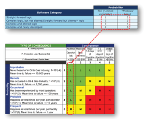
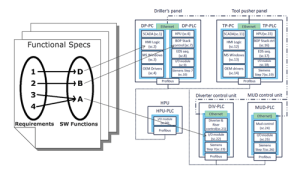
Figure 1 shows an example of a topology containing sequentially numbered software components.
Prepopulating the FMECA table
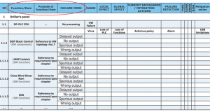
As a rule of thumb, use the lowest level of functions described in the functional design specifications, such as valve commands, interlocks, emergency disconnect system sequences, human machine interface (HMI) functions, watchdogs, etc. Table 1 shows an example of a prepopulated SFMECA table containing failure modes.
Fundamental SPFMs
The need for narrowing down the potential failure modes has been discussed in standards and literature. The approach discussed in this article proposes to narrow down the software potential failure modes (SPFMs) to four fundamental types:
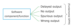 If the SPFM does not trigger interest during the workshop, it can be deleted. If the team is in doubt or demonstrates interest, it should be kept.
Risk/criticality matrix
The difficulty of using a common risk/criticality calculation matrix is not in determining the consequence categories but in mapping the scale of probabilities of failure. For hardware, manufacturer data and field experience is usually disposed of, but the problem is different for software. One way to address this problem is by using the following three criteria, joined by a fourth overriding one:
• Technology robustness: For example, Windows-based technology is known to have a higher failure rate than PLC-based technology…
• Logic complexity: The correlation between the logic complexity and defect-prone software has been validated in literature. When assessing a SPFM for its probability of failure, invite software engineers to categorize the software function’s complexity (e.g., straightforward logic, medium or complex).
• Proven in use: When a software module or function has been proven in use and is not subject to any modification (altered software should not be considered as proven in use), the probability of failure can be lowered because the software defects are more likely to have been identified and removed through the years of use in the field.
• Subject matter expert (SME) field experience: The probability of failure can be overridden by the SMEs depending on the team’s discussions as they may have field experience on known failure modes of certain software packages, etc.
In Figure 2, the above criteria were used to create a scale of 1 to 5, which maps to an example scale of a given hardware failure probability range.
Mutual effects of failures
It is worthwhile to assess the mutual effects of software and hardware failure modes. Designers of control systems should consider:
• How will the equipment react to a given software failure mode?
• How will the software react to a hardware failure, loss of sensor, erroneous sensor, sensor missing from design or faulty position of the equipment?
• Are there common mode failures being introduced by hardware redundancy (redundant hardware running same software)?
Break down critical functions
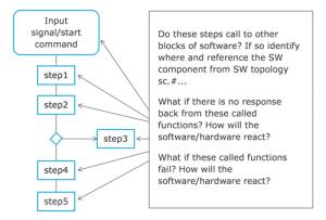
It is not practical to test all theoretical branches of software execution paths, which run up to 2n paths, where n is the number of conditions within a function. If this function contains conditional loops, the result may lead to an infinite number of paths. Inviting the SMEs to pre-select, zoom in and break down critical functions will help cover more ground at a minor cost and keep the teams’ attention fresh throughout the workshop.
One easy way to do this is to draft the flow chart of a function’s process flow and analyze what would be the cascading consequences of a function failing at a given step while considering software interlocks, timers, calls to libraries, detection of faulty sensors as in Figure 3.
Analyzing HMI failure modes
The facilitator should ask SMEs if there is logic embedded within the HMI or supervisory control and data acquisition (SCADA) that will be executed for a given command/push button as opposed to simple signals requesting the execution of software in a remote PLC. Crashing of the HMI at the wrong time can lead to undesired effects when an HMI is waiting for the completion of other code execution before completing a sequence or giving back the command to the operator.
Determination and tracking of mitigation actions
Members of the workshop are often tempted to lower the probability of failure of a SPFM because they assume the software is scheduled for testing before it leaves the factory (such as FAT, HIL testing). Mitigation actions must be considered as actions to be carried out and tracked via documented evidence confirming the mitigating verification and validation activities have been carried out.
Teaming up with the responsible software QA helps keep track of these actions. This is especially important for new software as the likelihood of failure of new software is at its maximum until all verification and validation actions have been carried out, including testing of failure modes.
SPFMs found during BOP SFMECAs
DNV has tested the proposed approach for BOP control system FMECAs on three occasions. The workshop duration was extended up to two extra days to address software failure modes using the proposed approach. A combined amount of 224 extra failure modes were identified, 11 of which were high risks, 22 were medium and 191 were low.
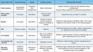
Table 2 provides a sample set of the types of software failure modes and mutual effects from hardware failures that were identified using this approach. These samples are examples of significant risks that could be mitigated at a minor cost. The first half of the table contains software failure modes while the second half contains hardware failure modes aggravated by software not being designed to handle the hardware failure.
Mitigation actions vary from simple additions of time-out logic in the software code to the implementation of software watchdogs and additions of more situational awareness logic to be described in the functional design specifications. The failure modes should be added to the testing program(s) where applicable.
Conclusion
As stated in IEC 60812, an FMECA should not be used as the single basis for judging whether the risk of a system is acceptably small. “More influential parameters (and their interactions) can be taken into account, e.g. exposure time, probability of avoidance, latency of failures, fault detection mechanisms.” However, this approach has been observed to add value to conventional methodology observed in the offshore industry, where system FMECAs often only address software failures via the failures modes of hardware hosting the software. DC
This article is based on a presentation at the 2015 IADC Critical Issues Asia Pacific Conference, 18-19 November, Singapore. An unabridged version of this article can be found online at www.DrillingContractor.org.


