Multiphase simulations enhance well designs, contingency planning
Advanced engineering tools allow complete wellbore modeling during kick circulation, blowout, dynamic kill
By Fred Ng, Wild Well Control
Events in recent years have heightened industry awareness regarding well control issues, especially high-pressure, high-temperature (HPHT) and deepwater drilling operations, which are becoming increasingly common in many parts of the world. Risk management involves developing mitigation and contingency options for identified risks. This article addresses applicable engineering tools that have resulted from development of advanced technologies in recent years. These tools include multiphase simulations to address well planning and kick tolerance evaluation for mitigation options, as well as simulation of blowouts and dynamic kill for contingency planning. They can be applied to land or offshore operations. The advanced technologies enable complete modeling of detailed conditions in the wellbore during kick circulation, blowout and dynamic kill. Case histories will illustrate and highlight such applications. Discussions will also include recent developments in equipment and systems for capping subsea blowouts, some of which are now in place for various regions globally.
A Risk Management Approach
Risks of many kinds are inherent in the hydrocarbon extraction business, and both operators and the service sector are expected to be diligent in making decisions regarding these risks. In particular, well control is an ever-present risk that requires continuity of vigilance both in time and phases of operations. These measures begin with pressure management in well design and operations on a day-to-day basis. A failure in pressure management can lead to a pressure control event where unconventional well control procedures and special expertise may be needed to handle scenarios such as an underground blowout. A blowout results from failure in pressure management and/or pressure control and may lead to extensive intervention efforts, as well as a relief well and dynamic kill.
Pressure Management
Wellbores are designed and constructed to manage expected formation pressures. Typical elements for the planning phase include evaluation of pore pressure, fracture gradient, mud weight, casing design and depth selection. In operations, the measures include monitoring well behavior and making adjustments to manage the pressures. Multiphase transient simulation for kick tolerance and other parameters is now available to meet the critical need for determination of a well’s capacity to handle kicks and other well control scenarios.
Pressure Control
This occurs when pressure management has been compromised by unexpected formation pressure or operational conditions. It can also result from complications, such as drill string washout, bit plugging or formation bridging, in an otherwise standard kick circulation. This often results in handling kicks with simultaneous losses or underground blowout, leading to a variety of unconventional well control operations that is best conducted by well control professionals. Multiphase simulations play an increasingly critical role in evaluation and design for pumping, bleeding and other options involved in these operations.
Blowout
A blowout results from failure in pressure management and/or pressure control and often leads to extensive intervention efforts, as well as relief well and dynamic kill. Advanced multiphase simulation is now available to support these efforts in a format that is suitable for practical application. Results include kill mud weight, volume required, kill rate, pump pressure, hydraulic horsepower and other critical factors. Such simulation is now also used widely to meet operator or government requirements for contingency planning, providing information on viability, design and operational requirements of the kill operation needed to resolve a blowout scenario. Equipment and systems for mud line intervention in subsea blowouts have also been developed for debris removal, dispersant application and blowout preventer (BOP) capping. They are now in place for various regions.
Multi-Phase Kick Simulations
Multiphase kick simulation is available to provide analysis of kick tolerance and other critical parameters, both for the well design and operational phase. Results are more accurate and versatile than the traditional single bubble calculations. The latter cannot include effects of compressibility and solubility of gas in oil-based mud systems, which are increasingly used in industry for the current generation of wells in HPHT environments. It involves a complete time transient multiphase flow simulator that models the full dynamic behavior of the wellbore and its contents. The model simulates a kick from time of influx, through flow check, shut-in and subsequent kill operations.
One typical application is kick tolerance evaluation. The technology allows such evaluation to be based on circulating out, not just shut in, of well kicks over a range of magnitudes and sizes. It can be used for both well planning and updating well design when conditions change during operations, such as target depth, pressure, mud weight or leak-off test results. Data from these simulations, which typically ran for all hole sections drilled through the BOP, can also be used to evaluate casing design, as well as surface well control equipment.
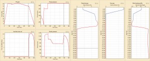
These simulations have been used often to support real-time well control operations. Results can be available within minutes for a well with a model that has been set up during its planning. A graphic output such as shown in Figure 1 can be transmitted both to the rig and the planning team in the office, thus facilitating the technical discussions that are typically needed in planning the kill operations. The simulations can be used to provide modeling and evaluation of different well control procedures besides standard kill methods, including extended shut in before or during a kill, volumetric kill to bleed gas to surface and maintain constant bottomhole pressure, and losing returns during a kill.
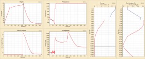
The kick simulations described in this article are run with the Drillbench simulator provided by SPT Group. Figures 1 and 2 show result graphics from an example of gas kick circulation, using Driller’s Method in a 27,300-ft HPHT well, with 15.0-ppg mud weight, a 0.7-ppg x 80 bbl kick and a kill rate of 200 gal/min. The case with synthetic oil-based mud (SOBM) is shown in Figure 1, and the same case with water-based mud (WBM) is shown in Figure 2.
Maximum Choke Pressure
This occurs when the top of the influx reaches surface. The pressure with SOBM is 1,250 psi, which is lower than the 1,350 psi seen at initial shut-in. With WBM, the trend is reversed, where the respective pressures are 2,200 psi and 1,450 psi. The main cause of the different trends is gas solubility in SOBM, which keeps the gas in solution until it reaches bubble point at about 3,500 ft, with free gas at less than 2% by volume at the surface just upstream of the choke. Much of the 11,500-ft influx column at that point is still dissolved in the relatively dense gas cut mud of 13.5 ppg. Gas solubility in WBM is lower, resulting in a free gas column of some 18,000 ft, with free gas reaching 30% by volume at the surface.
Pit Gain
In the case with SOBM, the dissolved gas continued to diffuse and stretch out in the mud column as it is circulated up the hole. The result is continuous reduction of gas cut in the mud column, causing pit volume to shrink from the initial 80 bbl down to 70 bbl before the influx reached surface. Since gas is much less soluble in WBM, the free gas has to be allowed to expand in order to maintain constant bottomhole pressure, resulting in an opposite trend where pit volume increased to 100 bbl.
Gas Migration
Gas migration occurs only when it is present in the form of free gas. In water-based mud, it occurs typically at the rate of 2,000 ft/hr to 3,000 ft/hr. In this case, the result is that the influx reached surface some four hours sooner in WBM than SOBM. Free gas migration in water-based mud continues even when a kick is shut in, resulting in equally rapid pressure build up throughout the wellbore, such as seen in the choke pressure plot in Figure 2.
If a kick in WBM has to remain shut in for an extended period, standard procedures such as volumetric kill should be applied to bleed off such pressure buildups accordingly to maintain constant bottomhole pressure and thus avoid breaking down the shoe. In the absence of such precautionary measure, it is not unusual to see a kick that otherwise could have been circulated out evolve into a complicated scenario of having to deal with underground crossflow.
For the same reason, it would be advisable to specify a limit for the initial shut-in period when evaluating kick tolerance in water-based mud. Typically, a period of 15 minutes or so should be sufficient for a crew to shut in the kick, note pressures and volumes and start volumetric or driller’s method operations.
Surface Mud Weight (SMW) vs. Equivalent Static Density (ESD)
Multiphase simulation provides complete modeling of the effects of temperature, compressibility, gas solubility and hydraulics under all conditions throughout the wellbore. These effects cannot be easily included in the simpler traditional models, which basically treat all kicks as single bubble water-based mud scenario. Under static conditions, the simulations provide a profile of the in-situ mud weight as well as ESD for the wellbore. In a typical HPHT well of over 25,000 ft, the SMW/ESD ratio in SOBM can be 17.5/17.7 ppg, versus 17.5/17.1 ppg for WBM. The reverse in trend is due to the difference in thermal expansion and compressibility of base oil versus water and can be critical factors in evaluating kick tolerance under these conditions.
Blowout simulation, dynamic kill design
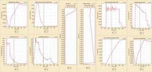
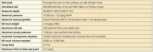
The multiphase flow involved in a blowout evaluation and dynamic kill design is very complex and can only be analyzed by transient flow simulations that take into account all the physical effects involved. The graphics in Figure 3 show a simulation for the blowout and dynamic kill of a 28,000-ft well. The well unloads until a steady-state blowout is established at about the 60-minute mark. Dynamic kill is initiated and pumped until completion, with the four windows on the left displaying pressure and flow rate data for the blowout well, and three on the right showing behavior of the relief well.
The simulations described in this article are run with the OLGA Advanced Blowout Control simulator, which was developed in a cooperative effort between Wild Well Control and SPT Group. It involves the latest technology in transient multiphase simulation and is particularly useful for today’s deep, HPHT and prolific wells.
While a parametric dynamic kill design can be developed for contingency planning, the actual design often has to be modified and established based on the circumstances of the blowout event and availability of equipment. For example, the maximum pump rate of 100 bpm in this case is likely to require special equipment and design for the surface spread, as well as for mixing, handling, transportation and storage facilities to support the kill. One operator is currently considering the design of a subsea kill spool in order to deliver such kill rate to the wellbore.
Blowout rate
This depends heavily on reservoir properties, as well as wellbore conditions and the scenario to be addressed, and is simulated as part of the dynamic kill design. For example, it can be an unrestricted or restricted flow and can range from blowout above the water line for a jackup to an uncontrolled flow from a wellhead on the sea floor.
Off-Bottom Kill
Depending on the distance of the intersect above the blowout zone, the required pump rate, kill mud weight and equivalent circulating density (ECD) for an off-bottom kill will all be significantly higher than for a kill on bottom. For example, kill mud weight and ECD can both exceed formation fracture gradient in the open hole, resulting in massive losses. If identified by simulation runs during the planning phase for the original target well, this problem may be addressed by running a deeper or additional string of casing or liner. Otherwise, options may be very limited if a blowout occurs.
Pump Rate and Control
In most cases, the blowout generates a substantial draw down in the original wellbore, resulting in a strong U-tube action whenever it is intercepted by the relief well. All efforts will be needed to prevent the relief well from unloading, by keeping the relief well full at a high pump rate. After the initial U-tube, pump pressure rises steadily as kill mud continues to fill the blowout wellbore. Pump rate must then be reduced in order to maintain wellbore pressure below fracture gradient and to keep pump pressure within ratings of the surface equipment. In this case, the operator had set a pump pressure limit of 7,500 psi, and the simulation shows how pump rate can be continuously stepped down to match it.
Equipment for Capping a Subsea Blowout
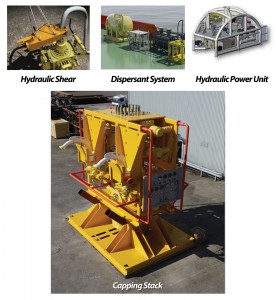
A statement from the US oil and gas regulatory agency BOEMRE highlights the need for such equipment: “To date, the primary deficiency that BOEMRE has identified in its review of OSRPs (oil spill response plans) is the lack of sufficient subsea containment equipment and other resources.” One such system recently made available is rated for 10,000-ft water depth and provides the equipment described below, which are modularized for air transport by cargo aircraft such as Boeing 747 or Antonov 124. Figure 4 shows the individual components.
Debris Clearing Equipment
Main components are hydraulic shears to cut the debris around the well. In the event that the rig’s lower marine riser package fails to separate during emergency disconnect, there is a high probability that the riser and other debris will hinder installation of the capping stack onto the primary drilling BOP. The largest of these shears typically has a jaw opening of 46 in.
Subsea Dispersant System
The system includes the distribution manifolds, hoses and applicators needed to deploy dispersant subsea. Subsea application of dispersant may reduce the amount of oil coming to the surface. This in turn could result in reduced exposure of surface vessels and personnel to volatile organic compounds of the oil. It may also reduce the need for surface recovery or in-situ burn, as well as expensive surface dispersant operations that can involve multiple vessels and/or aircrafts.
Capping Stack
A capping stack is a contingency device for well isolation used to cap a blowing well or to provide an engineered interface for flowback and disposal. It can be employed in the event of failure of the primary drilling BOP to shut in a well. It is mated to the primary BOP stack by connecting to the top profile of the BOP using a compatible connector. Once mated, the well can be shut in with the two blind/shear rams. Flowback to surface capture and disposal vessels can be conducted through its four 3-1/16 in. outlets. This is similar to the capping stack that successfully capped the deepwater blowout in the Gulf of Mexico in 2010.
Subsea HPU
This hydraulic power unit system delivers up to 50 gal/min at 5,000 psi and includes equipment for launch and recovery, deployment winches, as well as a surface control cabin. It is a complete stand-alone package, powered via dedicated remote operating vehicle (ROV) umbilical, and includes a control system that linearly adjusts the flow and pressure for each hydraulic output. The system is based on proven ROV technology, including acoustic monitoring of the capping stack pressure sensors, as well as back-up pumps to provide emergency hydraulic power utilizing seawater.
Experience indicates that such equipment functions best when deployed as a system, with active participation by specialists from the well control industry. Specialists are needed to provide critical knowledge and experience for developing plans and procedures, with identified and engineered interfaces and redundancies. While the proper equipment is required, professional resources can provide the critical difference to ensure a successful resolution of a well control event.


