Verification of rig power systems critical in software testing
Inspection after all systems are integrated can unveil conflicts in control logic/overlap, system parameters
By Adi Gildor and Cris DeWitt, ABS Consulting, an ABS Group Company
All figures courtesy of the International Marine Contractors Association’s Guide to DP Electrical Power and Control Systems
In offshore dynamically positioned (DP) drilling operations, power, thrusters and other systems are below deck and often out of sight. Yet, even small problems in these systems can drastically affect the drilling program. Often referred to collectively as “power” or “thrusters,” these are highly complex, interconnected and cohesive systems that generate large volumes of technical information. They comprise components, auxiliary equipment and multiple control subsystems that require constant observation and dedicated maintenance.
Before a DP system is put into service, an intensive commissioning and integration testing program follows the system from the original equipment manufacturer through the shipyard and into sea trials. Throughout the commissioning and acceptance testing process, independent third parties, such as a classification society or consultancy, verify that system components meet relevant technical standards and regulatory requirements. Third-party observers serve an important role in confirming a unit’s safety and seaworthiness by capturing issues that often lie outside the builder and owner’s testing processes.
Executing verification
The commissioning and acceptance testing process at its minimum should demonstrate system control and safety functionality of the stand-alone equipment. This process would ideally result in the optimal functional performance of these systems. However, factory acceptance tests, equipment commissioning and system acceptance tests are usually based on shore and harbor conditions, which do not accurately reflect the integrated operating environment of the power and thrusters systems.
Power and thruster systems demonstrate their true functionality and control when they are tested at their most complete levels of integration. This usually happens for the owner during sea trials and during system integration tests required by the operator/client. During maneuvering and power stress tests, the increased demand from other heavy power consumers onboard, such as cranes, drawworks, top drives and mud pumps, are introduced to evaluate the power system’s ability to manage output while dynamically maintaining the position of the vessel. Increased demands on the power and thruster control systems often identify unexpected consequences.
As part of ABS Consulting’s independent third-party inspection services, engineers observe and report situations in which mobile offshore drilling unit (MODU) equipment or systems do not perform as expected. When issues are identified, they are followed by more design review, engineering and enhanced testing.
Third-party reviews have discovered situations resulting from coordination issues among multiple vendors, issues that stem from customized expectations and problems caused by poor installation quality, testing competency, communication and project management.
The ultimate goal for the designer, builder and owner/operator is to resolve these issues before construction begins so there is no delay in vessel delivery and the costs to repair are low. Once the unit leaves the shipyard, the goal is to drill the first well without any lost time caused by system errors. Third-party observation that uses an integrated methodology to verify and test software risk throughout the asset lifecycle reduces the delay from shipyard to first well.
Power functionalities
Power keeps the offshore unit on station, supports drilling operations and supplies the needs of the crew. Power is expected to be available, reliable and maintainable throughout operations and to recover safely and effectively following a blackout.
In general terms, the system can be divided into the functions of generation, distribution and management, and each of these functions poses an opportunity for software issues to arise.
Power Generation
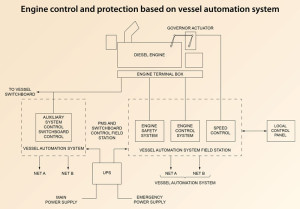
Power generation includes diesel engines and generators. Engines convert fuel to rotational energy that is transformed into electricity in the generator (Figure 1). Once generated, power is distributed from switchboards to transformers to variable frequency drives (VFDs) to consumer loads. All the while, the amount of voltage/current produced and its availability to the loads is controlled by the power management system (PMS).
Because consistent functionality is critical, these systems are among those that benefit from third-party observation during commissioning and integration testing.
In one instance, during temperature sensor testing for the engine and generator safety systems, a third-party inspector discovered that if a sensor were lost, alarms would signal a “High High” condition, causing the engine or the generator to shut down. In the case of a false alarm, a sudden shutdown could result in power loss and could potentially damage the engine. In this case, the issue resulted in a change in I/O failure handling logic to “freeze the sensor to the last legal value,” generate a “wire break” alarm in the dynamic alarm log and provide a color change of the sensor mimic in the vessel management HMI screen to indicate the process is in a fixed alarm state.
This solution avoided unwanted engine/generator shutdown resulting from control logic and provided a specific indication of the alarm state, cause and location. It also gave the engineer time to respond and provide a controlled shutdown while minimizing impact on the power available for operations.
The active power the engine generates to drive motors and resistive loads is an important component of the power, but there also is a need for reactive power. Reactive power provides the circular current that maintains magnetizing fields for transformers and motors to function. The electromagnetic field in the generator acts as a magnetic coupling through the electrical distribution network, connecting the active power from the engine to the electrical motor loads (drilling equipment, pumps, thrusters).
The generator that is driven by the diesel engine generates reactive power but, during varying power demand, requires a stronger magnetizing field in the generator (excitation of its field). What controls this excitation is the automatic voltage regulator (AVR). The AVR is not actively controlled by the PMS and has no direct operator interface during operations. It relies on its operating parameters and inputs from the generators and the voltage switchboards.
Reactive power is critical to safe and consistent operations and is one of the functions evaluated through third-party verification. In one instance, it was observed during a reactive load-sharing test during sea trials that critical electrical protections were not configured and enabled in the AVR, which could have resulted in a loss of sensing and loss of field.
Partial or total loss of field on a synchronous generator is detrimental to both the generator and the power system to which it is connected. The condition must be detected and the generator isolated from the system to avoid generator damage. A loss of field condition that is not detected and controlled can have a damaging impact on the power system by causing a loss of reactive power supply and creating a substantial reactive power drain. Without third-party verification, this situation would have been very costly in the field.
Power Distribution
Onboard switchboards and transformers have redundant electrical protection to safely receive and distribute electrical power to the loads. At a minimum, a power distribution system monitors voltage, current and frequency to assure they stay within the required capacity and tolerance. Fault conditions arise when any of these parameters is out of tolerance for more than an pre-determined period of time.
Electrical protections, such as sensors, relays, switches and circuit breakers in the distribution system, usually are well established and are verified during ship classification, commissioning, acceptance tests and sea trails. When protection controls experience overlap between systems (generation and demand), the power management system is expected to oversee and direct the appropriate control and action. Unfortunately, the balance of control is not always optimized.
An instance of control overlap was observed in the DP and PMS software that limited the amount of power available on each bus of a three-bus network. This 50% power limitation was created in logic by the DP and PMS software even though an electrical protection was in place on the switchboard that monitored a control parameter (frequency). The software power limitation command was engaged by a calculation and an arbitrarily set percentage limit. The frequency monitoring protection at the switchboard, on the other hand, is a direct measurement of the electrical bus’s ability to provide power. Control and protection from the switchboard was at the source of the detection, the closest location to isolate the power fault, and resultantly the fastest in engagement. The lesson learned is that software from the PMS can provide redundancy protections, but it also can create unwanted results, such as protection limitations that impede equipment operation.
PMS
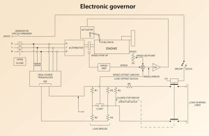
The PMS makes sure power is available and controls power consumption to avoid a blackout condition. Satisfying consumer loads with available power requires the PMS to issue commands to the engine governor system (Figure 2), which balances the load between engines. This load sharing is a safety measure that ensures power generation is distributed equally if an engine loses power, and increases output from the remaining engines to make up for the lost supply.
While the governor system works separately from the PMS to execute load sharing, it interfaces directly with the PMS. Because the PMS has its own parameters and settings for its operational logic in pursuit of satisfying load requests, what it communicates to the governor and the AVR regulates the engine and the generator output. And this creates the potential for control issues.
A case that illustrates this was uncovered when engineers onboard a vessel requested a change in the sequence for removing an unhealthy engine. Changing the sequence for taking the engine offline affected load sharing during the transition. The sequence in place would have allowed the PMS to reduce the load of the unhealthy diesel-powered generator (DG) and then to shut down. The proposed sequence would reduce the load and remove the DG from the bus while keeping it running so the engineers could troubleshoot the running engine. This approach also avoided a reverse power situation.
However, during the testing of this new sequence, the governor received a reduced base load signal from the PMS that resulted in all of the healthy engines reducing their base load similarly to the unhealthy engine. This caused all of the engines to function at 40% capacity. A reduction of this amount has the potential to seriously impact drilling and well control operations on the vessel and to compromise its ability to keep position. Ideally, the healthy engines should have increased their base load to compensate for the reduction in load for the unhealthy engine. The discovery of the fault in the load-sharing logic in the governors and the PMS allowed a potentially dangerous situation to be avoided.
Software and time
The incident above illustrates the potential for miscommunication or conflict in logic in cases where the PMS communicates with other systems. Timing and speed demands for communication determine the proper operation of the power system; sometimes, compromised communication is the result of the computational capacity of the PMS.
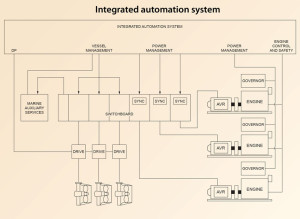
PMS software monitors the amount of power generated and consumed and controls how power becomes available (Figure 3). A huge volume of calculations and comparisons are processed by the software as it carries out these functions. If either the processing or the communication takes too long, it can be necessary to take protective measures to prevent downstream controllers from reacting to dated information that does not reflect current operational situation.
Software communication issues can result in situations that impact operational efficiency. Engineers discovered the effect this can have on a drillship. The vessel had two PMS chipsets for each switchboard, which amounts to an increase of 100% processing power for the same loads. Processing is performed by semiconductor logic chipsets in the controllers. The chipsets are located on the high-voltage switchboards receiving AC power generation from the generator sets. During sea trials, a PMS test using the main drawworks experienced a level of power consumption that exceeded the amount of power available.
This constitutes a power limitation/load reduction violation – which is based on sending a signal for maximum power available (kW) to the consumer (i.e., drawworks). It also requires load measurement – power consumed signal (kW) – to be interfaced to PMS field stations where load calculations are performed. Analyzing the violation led to the conclusion that the PMS could not calculate and transmit the “power available” signal as quickly as the “power consumed” signal was generated and processed.
This resulted in a limitation of operations on the drill floor, where the drawworks motors were requesting and consuming power at a rate that was more rapid than the control command power available signal of the power distribution system.
Generally, the protections within the 690V drilling drive switchboard provide a heavy consumer protection much more quickly and effectively than the PMS software. The lag in PMS calculations and transmissions resulted in an inaccurate view of power consumption. The 690V drilling drive that distributed the power was fitted to detect a drop in frequency resulting from an increase in power consumption that exceeded supply.
Thrusters
Dealing with faults in normal vessel operations usually is not as problematic as recovering from abnormal conditions.
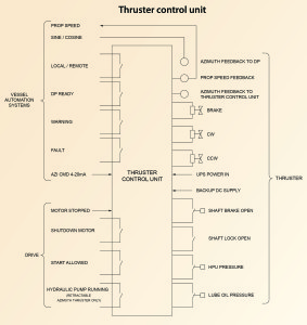
On a DP drillship, it’s critical to maintain normal operations (stationkeeping) for its thrusters, which constitute the largest and most critical loads (Figure 4). Transformers and VFDs regulate power delivery and control to the motors on the thrusters. Power is fed to the thrusters via several controllers among the VFD, DP field stations and the thruster controllers that are all working together.
Coordinating the controller commands requires verification of signal values and their timing, delays and/or duration.
The large power consumption of the thruster system necessitates multiple control and safety systems to maintain safe operation. During its operation, the thruster system is monitored similarly to the diesel engines (cooling capabilities, temperature of electrical and moving components, lubrication, etc).
Because thrusters perform as dynamic loads, rapid positional changes and sudden increases in power can be required to contend with changing environmental conditions that could diminish the unit’s ability to maintain station over the well. As the thrusters rotate and increase power, fluid dynamic forces can reverberate up into thruster shaft and into the driving motor. Excessive vibrations can trigger alarms and shut down the induction motor driving the thruster.
In the case of one thruster system, these vibrations occurred during some turns and during power load variations. Many unsuccessful attempts had been made to isolate and resolve the vibrations mechanically. The proposed solution was to change the timer in the protection software to allow for vibrations during power increases so system power would not shut down. While this software modification solution maintained performance integrity, it introduced the possibility of leaving the motor and thruster without adequate protection.
A holistic view
Commissioning and customer acceptance tests, FMEAs, sea trials, and system integration tests all work to confirm the quality of installation, the basic functions of individual equipment and successful equipment and system integration. However, the true test of system integrity is passed when all of the equipment and systems function seamlessly in real-world operations. This requires the software controlling the systems to provide useful and timely information to maintain safe operations and enable speedy recovery when things go wrong.
While there are many involved personnel that support structured plans and processes for the whole design, build and verification of a vessel, third-party verification provides a perspective that is not compromised by financial and organizational challenges that can influence the builder and the owner.
This article is based on a presentation at the 2014 IADC Advanced Rig Technology Conference, 16-17 September, Galveston, Texas.
Click here for more information on the IADC Contracts & Risk Management Conference



In deed it is good article. The problem of high demand power for Thruster and Draw works can be eliminated with Ultra capacitor banks.
Ofcourse it will little increase the complexity of system , however it is justifiable against the complete black out or limitation in drilling operation.
The slowest device in power measurment chain are analouge relay which take longer time ..do we have faster relay available in market?