BP develops customized riserless light well intervention system to handle deepwater challenges
Upgrades extending the operability window of system components allowed the operator to go riserless while maintaining efficiency


By Stephen Whitfield, Associate Editor
Riserless light well intervention (RLWI) systems are gaining popularity as a means to increase production from offshore assets. Unlike conventional riser-based light well intervention systems, riserless systems give users wireline tooling access and the ability to control the wellbore without the need for an access conduit that connects a well’s direct vertical access point to the intervention vessel. This can lead to quicker turnaround times and less financial investment needed.
However, using RLWI systems in deepwater operations can bring on other challenges related to the stresses placed onto the system components, which can create limited operability windows for the system. In order to improve efficiency and increase the operability windows in RLWI systems for deepwater operations, existing systems must be customized, said Michael Ge, Subsea Wells Analysis Lead – West Hemisphere at BP.
“The operational risks with riserless systems are not fully understood, and the operational windows may cause significant downtime due to the system’s limitations in unfamiliar environments. We need to assess the limitations of these systems, and once we’ve done that, we need to do something about it to improve it,” he said.
Speaking at the 2023 SPE/ICoTA Well Intervention Conference in The Woodlands, Texas, on 21 March, Mr Ge discussed BP’s efforts to develop a customized RLWI system for deepwater operations, outlining both development challenges and testing results.
Challenges with RLWI systems
Utilizing RLWI systems in deepwater can be challenging because, for one, the coiled-tubing downline systems are subject to significant dynamic movements due to wave loadings, ocean current and vessel movement. The stresses placed on these systems are greater in deepwater compared with the shallow-water operations in which these systems are typically employed. Over time, these stresses can decrease the system’s efficiency. Further, the integration of umbilical, wireline and pressure control equipment can place constraints on the system’s operability windows and decrease the system’s efficiency.
Mr Ge also noted that, for an RLWI system, as many as eight downlines may be suspended simultaneously during operations. In a conventional riser-based LWI system, these downlines would typically be clamped to the riser at regular intervals to control against the dynamics of the ocean environment. In a riserless system, these downlines face an increased risk of clash, entanglement and damage, particularly in a deepwater operation, where more of each line would be needed compared with shallow water.
“When you look at a subsea field, it can be very congested,” Mr Ge said. “There are a lot of wells, a lot of manifolds, jumpers, trees. It’s a challenging environment, and you’ve got potentially high surface currents near the sea floor that can create significant challenges on the operations. It would be great to have a turnkey solution that handles these challenges, but they haven’t worked out very well.”
Designing an effective RLWI system for deepwater required BP to better understand the operability windows for each component within the system – specifically, looking at which variables in an ocean environment have the greatest impact on operability – and assess which components have sufficient strength to operate in a deepwater environment. It also sought to optimize hardware capacity and system configuration to improve operability windows and reduce nonproductive time in utilizing the RLWI system.
Equipment upgrades
As part of its analysis of the RLWI, BP developed a model to analyze the properties and boundary conditions of RLWI components. One component the model identified as a trouble spot for deepwater operations was the injector guide of the coiled-tubing downline system. Engineering analysis concluded coiled-tubing stress can cause damage to the non-metallic material that typically lines the inside of the injector guide.
BP used a 3D finite element analysis model to examine how the geometry of injector guide designs and the material used in each design can affect coiled-tubing stress. From that analysis, it was determined that a “split” design, in which the upper portion of the injector guide is made of conventional non-metallic material and the lower portion is made of steel, provided the smallest levels of coiled-tubing stress compared with other designs that were tested.
BP also performed fatigue analysis to analyze long-term wave-induced and current-induced fatigue on an LWRI system. It found that the most fatigue-critical spot in the system was on the coiled tubing, just below the injection head. To mitigate fatigue risk, BP installed a passive monitoring system on the coiled tubing, with one sensor being installed near the surface (up to 150 ft depth from the waterline) and another installed on the clump weight at the seabed. The company also installed real-time data loggers both below the injector head (where the most fatigue-critical spot was located) and on the vessel.
Mr Ge said that constant monitoring of fatigue can help limit nonproductive time by providing a more accurate picture of the state of the RLWI system. “We want to see the responses of the coiled tubing and the vessel itself. This allows us to better understand and calibrate the system to respond, say, to a severe wave or something else in the environment that can cause fatigue, so that we can mitigate the fatigue on the system quickly.”
Well-specific operating guidelines were also developed for the deepwater field where BP planned to test the RLWI systems. The company ran operability analyses to identify system weak points and create operational boundaries for numerous conditions, such as weather or heading excursions (deviations from the established vessel path). The operational boundaries were then summarized in a single document so it could be easily updated.
Through these analyses, BP also defined allowable heading excursions for a given LWRI system. Mr Ge said that BP had previously identified limitations on LWRI components given various surface currents and wave heights in its finite element analysis. However, it also found that creating hard boundaries around the vessel’s heading could inaccurately limit the vessel’s operability windows.
System testing
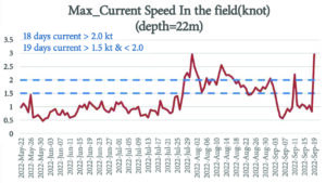
BP ended up testing the updated RLWI system in a deepwater well in the US Gulf of Mexico, operating at 6,825-ft water depth, from 22 May to 19 September 2022. Mr Ge noted there was “significant improvement” on the operability windows with the updated system. Based on its operability analysis, BP determined that the allowable surface current for the updated system was 2.5 knots, an increase over the 1.5-knot current limitation of the off-the-shelf riserless system it used on the well in an earlier four-month-long testing period.
This increase in allowable surface current increased the number of days BP could operate the system. During the four-month testing period, the company noted 37 days in which the surface current was at 1.5 knots or greater. This led to a 25% increase in operation time compared with the off-the-shelf riserless system used previously.
BP says it plans to utilize the updated system on other offshore well intervention projects. The company is also examining which updates can be transferred to other deepwater environments. “Even though it’s easy to think that the metrics are transferrable, each system has its own unique features that you have to consider, and these features create more challenges,” Mr Ge said. “We need to understand the system’s limitations so that we can improve the system’s operability in any environment.” DC
More information can be found in SPE 212915, “Enhancing Riserless Light Well Intervention Operability from Operator Perspective.”


