Taking holistic approach to designing cement sheaths helps maintain zonal isolation for life of well, increases ROI
Engagement of well lifecycle stakeholders is critical to cement design engineer
By Axel-Pierre Bois, Gregory Galdiolo and Anthony Badalamenti, CURISTEC

A cement sheath should be designed to provide sufficient hydraulic bonding to prevent micro-annuli and with the required mechanical properties to ensure complete zonal isolation for the life of the well. Engineering analysis and laboratory testing conducted prior to drilling the well is essential to obtain:
• A successful primary cementing job that delivers complete cement placement;
• A cement sheath that prevents fluid flow during cement hydration; and
• A cement sheath that withstands anticipated stresses during the life of the well.
This reduces total well cost and decreases the time to harvest the reservoir.
More than ever, financial institutions are requiring increased returns on their investments. Oil and gas producers are seeking larger reservoirs with higher delivery rates. Many of these new reservoirs are in areas that present unique technical and operational challenges, such as ultra-deepwater, high pressure and/or high temperature, extreme extended reach, brownfield redevelopments, etc. The cost for finding and harvesting oil and gas reservoirs is increasing, which also affects shareholder value.
Oilwell cementing can have a dramatic impact on a well’s economics. A successful primary cement job that maintains zonal isolation throughout the life of the well can not only reduce the well’s construction cost (CAPEX) and production cost (OPEX) but also decrease the time required to harvest the reservoir, which translates to higher returns on investment (ROI). However, a failed cement sheath can lead to loss of production from inner-zonal fluid flow or well shut-in due to safety issues. In many cases, it is difficult to repair a failed cement sheath, and this may require an expensive workover program and subsequent recompletion of the well. In extreme cases, a failed cement sheath can result in loss of reservoirs due to early well abandonment.
Achieving a successful primary cement job is hard, and achieving complete zonal isolation for the life of the well is even harder. Many times, a primary cement job design is based solely on requirements to support well construction and possibly well completion activities. However, designing an efficient cement sheath requires a holistic study of the anticipated stress changes in the well during its entire life.
In the past 15 years, new tools and technologies have been developed that enable today’s engineers to design innovative primary cementing to meet these technical challenges and help wells meet their financial goals. Examples of new primary cementing tools are dynamic temperature models, casing centralization models, fluid migration models and 3D hydraulic simulators based on computational fluid dynamics (CFD). These tools are targeted at achieving a higher order of cement placement in the annulus and preventing cement channels caused by either cement placement or fluid flow through the cement slurry during setting.
Cement mechanical integrity (CMI) models enable the engineer to view and study how changes in wellbore pressures, temperatures or reservoir properties affect the cement sheath design and analyze if the design is able to successfully withstand these changes. These models are used by engineers to identify the required mechanical properties that a cement design should have to maintain zonal isolation during the life of the well, including well abandonment. When using a CMI model, the engineer should try to obtain as much well lifecycle data as possible. He or she should engage not only the drilling and completion engineers but also include insights from production, reservoir and formation evaluation engineers.
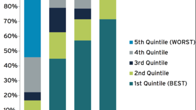
These engagements with all the stakeholders enable the engineer to develop a holistic view of the anticipated changes in wellbore and reservoir stresses during its life (Figure 1).
Early CMI models used well and cement data to determine if the cement design would either pass or fail due to debonding, tensile or shear damage. The processing time for these models was often extensive. Recent industry cement integrity R&D studies and field applications are providing a better understanding of the mechanics of cement sheath failure, as well as actions that can prevent the loss of zonal isolation. These studies have led to new modeling techniques, which not only increased the accuracy and reduced the processing time but also made simulation reports easier to analyze.
To highlight the main points of a good CMI model, consider the following example: A production casing cement sheath is designed with a compressive strength (CS) value of 30 MPa (4,350 psi) and a tensile strength (TS) value of 3 MPa (435 psi). The undamaged domain of this cement sheath is limited to between -3 to 30 MPa (from -435 to 4,350 psi). Well completion plans require that:
• The production casing be pressure-tested to 10 MPa (1,450 psi), and
• The drilling mud be changed out with a lighter-density completion fluid that will reduce the wellbore pressure by 5 MPa (725 psi).
Let’s assume, for the sake of simplicity, that a variation of wellbore pressure of 1 MPa (145 psi) is equivalent to a change of stress in the cement of 1 MPa (145 psi).
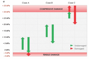
In this example (Figure 2), a stress variation path is considered, whereby stress is first increased and decreased by 10 MPa, (1,450 psi) before being lowered by 5 MPa (725 psi). If the initial state of stress is 0 MPa (0 psi) (see Case A), the pressure test will not damage the cement sheath. However, swapping to a lighter-density completion fluid will damage the cement sheath in tension because the final stress is -5 MPa (-725 psi), which is less than the TS value. Conversely, if the initial state of stress is 10 MPa (1,450 psi) (see Case B), the completion plans will not damage the cement sheath because the stress will remain in the interval from -3 to 30 MPa (-425 psi to 4,250 psi).
Finally, if the initial state of stress is 25 MPa (3,635 psi) (see Case C), the completion plans will damage the cement sheath because the final stress is 35 MPa (5,007 psi), which is higher than the CS value. This example demonstrates why the engineer should consider all well activities when designing the annular cement sheath and how important it is to know the correct initial stress state in the cement after it has set. Mistaking the initial state of stress can lead to a cement design that can fail.
There are five requirements for a good CMI model. The initial state of stress after cement has set is the first key point. The second key point is the ability to evaluate where the cement design lies in the safe working envelope and how close it is to the envelope limits. This requires the ability to quantitatively simulate all loadings to which the cement sheath is submitted during its life. The third key point is the capacities to simulate the stiffness and failure behavior of all materials in order to, for example, correctly locate the failure criterion limits.
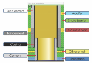
The fourth key point is the ease with which engineers can conduct sensitivity analyses, which help them to identify well activities that can damage the cement sheath and define the optimal cement properties requirements for complete zonal isolation. The fifth key point is the quality of the output charts. Hence, some CMI models determine the safe operating boundaries for the proposed cement design. These operating boundaries indicate where the proposed cement design resides within a safe working envelope and what is the safety factor for the cement design. Others also allow visualizing the entire cement sheath, with location of aquifers, in order to know where are the geological barriers that should be preserved (Figure 3).
Since no two wells are alike, it is important to design primary cement slurries to meet the specific requirements for each well.

Industry studies have led to the development of new cement mechanical property modifiers, which have decreased the cement slurry design and laboratory testing time, reduced onsite operational complexities and, in some cases, provided self-repair capabilities. Today, engineers have access to libraries of mechanical property data for various cement designs, which can be used in initial simulations.
However, to validate that the final cement design has the required mechanical properties, engineers should measure the true set-cement mechanical properties: not only Young’s modulus but also Poisson’s ratio, cohesion and friction angle. This requires manufacturing cylindrical samples and loading them in uni-axial and tri-axial pressure cells for the sample to be submitted to radial and axial stresses as encountered downhole, during the life of the well. The test results indicate if the cement design can withstand these stresses without failing and how much the cement deforms.
The most significant set-cement parameters are:
• Elastic properties, such as Young’s modulus and Poisson’s ratio, which are measured during uni-axial or tri-axial test phases where only the axial load is changed;
• The compressive failure properties, such as uni-axial compressive strength and friction angle, which are measured when pushing tri-axial tests to failure; and
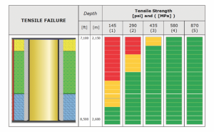
• The tensile failure property, which is measured with dogbone or Brazilian tests.
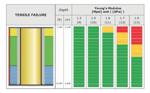
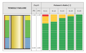
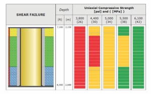
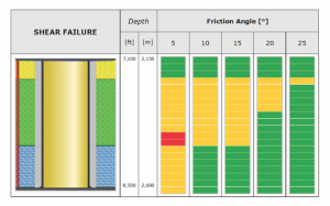
This is illustrated in Figures 4 to 8, which are synthetic examples based on real values. In each figure, the column charts on the right illustrate the risk of damaging the cement sheath along its entire length, for a given hypothesis. The green color means that the cement is far from being damaged, the orange color means it is on the edge of being damaged, and the red color means it definitely is damaged.
Conventional design workflow to ensure cement sheath mechanical integrity consists of three stages (Figure 9).
Appraise/select stage:
• For each cement sheath, perform CMI modeling to evaluate if there is a risk of losing integrity during the life of the well;
• For each critical cement sheath, compute the working envelope in which cement-mechanical properties should be located to ensure integrity; and
• Give the working envelope to service companies to select their best design.
Define stage, for each critical cement sheath:
• Measure cement properties to check if cements are in the envelope;
• Re-run CMI model to check if the cement design can ensure cement sheath mechanical integrity; and
• The goal is to select designs that can be tuned to ensure cement sheath integrity, and to help tuning them, and check them.
Execute:
• Quality control of the cement design.
In conclusion:
• You only have one chance to cement a well correctly.
• Loss of zonal isolation results in costly repairs, loss of production and, in severe cases, loss of reserves.
• The cost to repair a failed primary cement job is critical compared with the gains made by reducing design expenses.
• Maintaining zonal isolation for the life the well increases the well’s ROI.
• Engagement of well lifecycle stakeholders is essential for the cement design engineer.
• Cement integrity studies have led to new design tools and cement mechanical modifiers.
• Historical primary cement design methods may not be sufficient to obtain zonal isolation for the life of the well.
• New cement placement and integrity tools enable engineers to develop a higher order of primary cement success and zonal isolation systems for the life of the well.
• Tri-axial load cell testing provides validation of the cement sheath design. DC

