Study targets potential for gas loading in drilling fluids to improve influx detection, management
For flow check operations in overbalance situations, gas loading into fluid and volume expansion recorded topside are affected by actual state of gas-loaded drilling fluid
By Harald Linga, Knut Steinar Bjørkevoll and Jan Ole Skogestad, SINTEF Petroleum Research/DrillWell; Arild Saasen, Aker

Well control is a continuous and top priority for maintaining safe and efficient drilling operations. Particularly during deepwater and HPHT drilling, potential gas kick situations can be more difficult to detect topside due to the expansion potential of reservoir influxes. To detect gas influxes, knowledge of the interaction between natural gas and the drilling fluid at relevant process conditions is critical.
Although gas influxes are more severe in underbalance situations, a gas influx into the drilling fluid can occur in overbalance situations. This is the case where the drilling fluid has a large loading capacity of natural gas and is exposed to the reservoir gas via the filter cake, with diffusivity favoring natural gas flux. Such an influx can destabilize the drilling fluid and introduce barite sag. Sag of any type of weighting agents can sufficiently reduce the drilling fluid density to allow for a large influx of gas. Thus, there is an accelerating effect of dissolving gas into the drilling fluid.
Company rules of thumb exist for how to treat oil-based drilling fluids (OBDF) to avoid sag. It’s anticipated that at least one passage of the fluid through the drill bit with a pressure loss of at least 50 bar (725.2 psi) is needed to make a stable fluid. Further, experience indicates that sag is likely if the drilling fluid is diluted with more than 5% freshly made drilling fluid. Still, the detrimental effect from diffusion of gas will be important.

The gas-loading capability of OBDFs far exceeds that of water-based drilling fluid. As potential natural gas loading is more pronounced in higher-pressure conditions, care should be taken when handling OBDFs. In particular, the ability for early detection of gas influx into the drilling fluid should be considered.
The gas-loading capability of two classes of drilling fluids – one built with refined “normal” mineral base oil and the other with linear paraffin base oil – were the subject of a previous study. The latter fluid is often used in HPHT drilling applications. Two realistic flow check scenarios based on experimental gas solubility data were demonstrated, illustrating the importance of gas solubility characteristics to gas kick precautions. As the drilling fluid with linear paraffin base oil entered into the dense phase regime, with unlimited gas solubility, the linear paraffin base oil drilling fluid was considered less suitable compared with the drilling fluid using refined “normal” mineral base oil for detecting gas influx at elevated pressures.
Phase Diagrams
OBDFs represent essentially a mixture of hydrocarbon and water, which, for pressure (p) and temperature (T) conditions relevant for drilling, remains as a liquid phase. As natural gas, such as methane, is loaded into this hydrocarbon mixture, the region vs p and T for which the mixture remains as a pure liquid is reduced. It becomes important to determine for what combinations of p and T the mixture exists as a pure liquid mixture, as a combination of gas and liquid, denoted as a gas mixture.
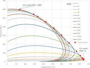
A phase diagram can be associated with the actual gas mass loading of the drilling fluid in concern. Gas mass loading is commonly expressed in terms of the volumetric gas-oil ratio (GOR), or Sm3/m3. Figure 1 shows an example for refined normal base oil.
The two-phase envelope is defined by the bubble point and dew point curves, which meet at the critical point. At pressures above the bubble point curve, the mixture exists as a liquid phase. For pressures below the dew point curve, the mixture exists as a gas phase. Inside the two-phase envelope, the relative fraction of gas and liquid depends on the combination of p and T.
When both p and T are above the critical point, the mixture of methane and drilling fluid exists as a dense phase, also denoted as the super-critical state. The dense phase is a uniform mixture of gas and drilling fluid, featuring different density sensitivity to pressure than the liquid phase.
The transitions between the gas or liquid phases toward the dense phase region are continuous in terms of fluid properties. This is in contrast to the transitions between the two-phase envelope to the liquid and gas phases, where the density sensitivity vs pressure characteristics changes.
The increase in density sensitivity vs pressure when reducing the pressure is associated with entering the two-phase region at the bubble curve. The change in sensitivity is less pronounced as GOR increases. Figure 3 shows that the lower pressure limit for the dense phase isn’t very sensitive to the actual GOR of the methane–base oil mixture for lower GOR. Therefore, when reaching the dense phase for a given pressure, the mixture remains in the dense phase when increasing the GOR of the mixture. Accordingly, the dense phase represents unlimited gas-loading capability. This is in contrast to the liquid phase, where free gas in equilibrium with liquid will appear when exceeding the maximum gas loading of the base oil in concern.
Time Evolution of Gas Influx into Drilling Fluid
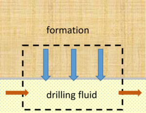
Appendix A (see article footnotes for web link) investigates the gas diffusion rate from the reservoir via the filter cake to the drilling fluid in the wellbore in overbalance with the surrounding reservoir. The mass transfer scenario over the filter cake is illustrated in Figure 4. It shows that for methane-drilling fluid at pressures below the dense phase region, the gas mass (mG) absorbed into the liquid is described as:
H is Henry’s constant for the natural gas – drilling fluid, p is the pressure, t [s] is time, A [m2] is the filter exposure area where the gas influx takes place, k is the diffusion constant associated with the filter cake characteristics, and mL is the drilling fluid liquid mass loading for the gas influx section.
Similarly, for the dense phase region of the natural gas-drilling fluid, where the gas loading is unlimited, the time linear relation of loaded gas is obtained:
Gas Influx during Flow Check
A flow check is defined as a period where operations, such as drilling, tripping pipe and circulation, are stopped, and the well is monitored to see whether it is static. The duration of a flow check should be enough to confirm the status of a well, which might be a few minutes or as long as 30 minutes. Many operators require 15-min flow checks if the well is in normal condition. On a particular well operation, a very small influx of gas was observed. Therefore, the drilling fluid density was increased to the anticipated maximum, and a flow check was conducted for a few hours. Still, influx of gas was observed. This influx, however, was later attributed to diffusion of gas.
Case Example
To draw attention to flow check scenarios and illustrate the continuous influx of gas, this influx scenario was considered:
• Process conditions: 600 bar (8,702.3 psi)/150°C;
• Influx zone: 10-m length, 8 ½ in. diameter, with constant diffusivity 5·10-3 kg·m−2·s-1 for the mud filter cake throughout the gas influx process;
• Gas-loading capability, two cases:
1. Gas solubility according to Henry’s law, gas loading into liquid. Henry’s constant experimentally determined to 0.414 g/(kg·bar) for the loading of methane into the base oil of the drilling fluid.
2. Gas influx in the dense phase region; solubility not limiting the gas influx.
For approximately the first two minutes, the loading performance was observed to be similar for the liquid phase and dense phase case. However, due to the loading limitation for the liquid phase case, the gas loading for this case arrives asymptotically at slightly above 5 Sm3, whereas for the dense phase case the gas loading increases linearly with time, reaching 25 Sm3 after 30 minutes.
During the flow check, the gas influx expands the loaded volume of drilling fluid, but due to the small liquid volume exposed to gas, the actual volume expansion in the bottomhole is less than 15 l for the gas loading in the liquid phase, not detectable topside during the flow check duration. For the dense phase, the local volume expansion is some 70 l after 30 min and approximately 500 l if the flow check period is extended to 4 hrs.
For such an influx, the volume expansion downhole, representing a topside gas volume of 230 Sm3, will be on the limit to be detected topside with present methodology.
When circulating after the flow check subject to gas influx, the fully gas-saturated drilling liquid will release free gas immediately as it’s exposed to reduced pressure during the circulation. Taking into account the accuracy of conventional topside kick detection systems, this will not be immediately detected topside. The situation is worse for the dense phase case, where gas will not be released until the gas-loaded drilling fluid has reached a wellbore position corresponding to bubble point.
Discussion
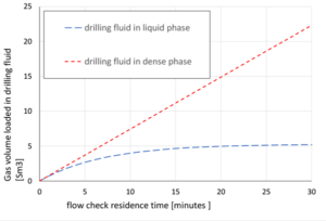
The diffusivity constant determines how fast the asymptotic gas-loading level is reached for the liquid case and is, in particular, influencing the initial gas-loading rate into the liquid phase. For the dense phase case, the rate of the gas loading into the drilling fluid is proportional to the diffusivity constant. For a flow check operation where a linear volume expansion is recorded topside and the drilling fluid is in overbalance with the reservoir, this may indicate that there is a continuous gas influx process in progress in the region where the drilling fluid-reservoir gas is in dense phase. Accordingly, special precautions should be taken with respect to identifying the drilling fluid dense phase characteristics when interpreting flow check operations during HPHT drilling.
Conventional kick detection systems rely heavily on monitoring topside pressures and fluid volumes. If a kick is suspected, a flow check is performed. In HPHT conditions, there is potential for substantial amounts of gas to flow into the well during the flow check procedure.
Additionally, the conventional approach does not properly account for fluid expansion and compression due to pressure and/or temperature effects. Thus, false alarms and downtime may be triggered. In the context of deepwater drilling, better instrumentation and improved fluid and wellbore modeling should play key roles in advancing kick detection technology. By coupling downhole instrumentation and advanced models, taking into account fluid compressibility, phase behavior and gas-loading capability, a more robust kick detection system that allows early detection and fewer false alarms is possible.
The effects discussed in this article become more pronounced and more important as pressure increases. To understand the relevance of this, let’s look at pressures and temperatures seen in actual HPHT fields.
Worldwide, there are many cases where pressure exceeds 1,000 bar (14,503.8 psi) and even 1,300 bar (18,854.9 psi). Conditions on the Norwegian Continental Shelf are less extreme, but even in this region there are important fields representing pressures between 750 and 950 bar (10,877.8 and 13,778.6 psi) and temperatures ranging from 120 to 200°C. With reference to data shown in Figure 3, representing a typical combination of a base oil and a reservoir fluid, it’s expected that for many types of drilling fluids, conditions may be encountered where the drilling fluid is deep into the dense phase region as combined with the reservoir gas.
For such cases, there is a severe potential for gas loading in the drilling fluid during a long stationary period. Details of dense phase should be well understood and incorporated into state-of-the art well control mathematical models. Proper procedures and/or algorithms for tuning of calculation versus PVT/kinetics measurements at relevant conditions should constitute an important part of doing accurate calculations.
Conclusions
For many types of drilling operations, conditions may be encountered where the drilling fluid is deep into the region where there is severe potential for gas loading in the drilling fluid during a long stationary period, such as during a flow check.
It is shown that for flow check operations in overbalance situations, gas loading into the drilling fluid and the volume expansion recorded topside are affected by the actual state of the gas-loaded drilling fluid, dense phase or liquid phase. For HPHT drilling operations, the gas influx during an overbalance situation may become considerable, in particular for the gas-loaded drilling fluid being in the dense phase.
The phase diagrams as calculated for mixtures of OBDF-methane demonstrate that there is a potential for arriving at dense phase conditions at 400-600 bar (5,801.5-8,702.3 psi) onwards, depending on the temperature and base oil. The dense phase condition has potential to maintain unlimited loading of natural gas caused by, for example, natural gas diffusion from the reservoir to the drilling fluid during an overbalance situation. This can cause gas influx not easily detectable topside until the gas-loaded drilling fluid has reached wellbore conditions representing the bubble point of the gas-loaded drilling fluid.
Due to the high gas-loading potential of the drilling fluid at high pressures, or when the drilling fluid is in liquid phase, care should be taken for addressing the kick potential and its impact on volume expansion recorded topside during flow check operations. This is particularly important as the local gas influx downhole during a flow check operation is not easily detectable with conventional topside kick detection systems. DC
Acknowledgement: The authors acknowledge the Research Council of Norway, Aker BP, ConocoPhillips, Lundin Norway, Statoil and Wintershall for financing the work through the DrillWell – Drilling and Well Center for Improved Recovery, a research cooperation between IRIS, NTNU, SINTEF and UiS.
References
Bradley, N.D., Low, E., Aas, B., Rommetveit, R. and Larsen, H.F. 2002. Gas Diffusion – Its Impact on a Horizontal HPHT Well. Paper SPE 77474 presented at the SPE Annual Technical Conference and Exhibition, San Antonio, Texas, 29 September – 2 October
Flatabø, G.Ø.; Torsvik A.; Oltedal V.M.; Bjørkvik B.; Grimstad A-A.; Linga H. 2015. SPE-173865-MS. Experimental Gas Absorption in Petroleum Fluids at HPHT Conditions. SPE Bergen One Day Seminar held in Bergen, Norway, 22 April 2015
IHS Markit. 2016. https://www.ihs.com/Info/en/e/pressure-studies.html Approached 14 November 2016.
Jacobs, T. (2015). Early Kick Detection: Testing New Concepts. J. of Petroleum Technology, Aug. 2015, pp. 44–49. Johnson A., Leuchtenberg C., Petrie S. and Cunningham D. IADC/SPE 167990. Advancing Deepwater Kick Detection.
IADC/SPE Drilling Conference and Exhibition held in Fort Worth, Texas, USA, 4–6 March 2014
O’Bryan P.L., Bourgoyne A.T., Monger T.G. and Kopcso D.P. An experimental Study of Gas Solubility in Oil-Based Drilling Fluids. SPE Drilling Engineering, pp. 33–42, March 1988
Linga, H., Nilsen F. P., Knudsen, B. L. Prediction Model Optimises H2S Scavenger Injection Strategy. Sulphur 2003, November 02-05, 2003, Banff, Canada.
Linga, H., Torsvik, A. and Saasen A., 2016. Kick Detection Capability of Oil-based Muds in Well Control Situations.
SPE-180039-MS, presented at the SPE Bergen One Day Seminar, Bergen, Norway 20 April 2016.
Omland, T.H., Saasen, A., Zwaag, C.v.d. and Amundsen, P.A. 2007. The Effect of Weighting Material Sag on Drilling Operation Efficiency. Paper SPE 110537 presented at the 2007 SPE Asia Pacific Oil & Gas Conference and Exhibition, Jakarta, Indonesia, 30 October – 1 November.
Saasen, A. 2002. Sag of Weight Materials in Oil Based Drilling Fluids. Paper IADC/SPE 77190 presented at the IADC/ SPE Asia Pacific Drilling Technology, Jakarta, Indonesia, 9-11 September.
Skogestad, J.O., Linga, H., Bjørkevoll K.S. and Saasen A., 2017. Methodology for Predicting Gas Loading Capability in Oil-based Drilling Fluids. SPE-184710-MS, SPE/IADC Drilling Conference and Exhibition, The Hague, The Netherlands, March 2017.
Torsvik, A., Skogestad J.O. and Linga, H., 2016. IADC/SPE-178860-MS. Impact on Oil-Based Drilling Fluid Properties from Gas Influx at HPHT Conditions. IADC/SPE Drilling Conference and Exhibition held in Fort Worth, Texas, USA, 1–3 March 2016.
This article is based on SPE/IADC 184686, “Gas Influx into Drilling Fluids During Flow Check Operations as Affected by Gas Absorption Characteristics of the Drilling Fluid,” 2017 SPE/IADC Drilling Conference, 14-16 March, The Hague, The Netherlands.
Appendix A
Kinetic theory related to gas absorption into liquid
The reaction between sour gas, concentration CG [mole/m3], and the solvent liquid, concentration CL [mole/m3], in a control volume can be described in terms of a first order reaction within a volume segment of the reaction volume,
where K is the specific rate of reaction [m3/(mole·s)] its numerical value depending on the actual types of gas and liquid and the exposure area (phase distribution) of gas towards liquid (Linga et al., 2003). The terms CG and CL represents driving forces for the reaction between the sour gas and the liquid solvent.

Analogously to this, ref. the control volume illustrated in Fig. A-1, the gas diffusion rate from the reservoir via the filter cake to the drilling fluid in the wellbore, in overbalance with the surrounding reservoir, can also be described by a first order reaction where the mass transfer rate over the filter cake is given by
where t [s] is time, mG is the gas mass loaded in the drilling fluid, A [m2] is the filter exposure area where the gas influx takes place, k the diffusion constant associated with the filter cake characteristics, and l is the gas mass loading in the drilling fluid per unit mass of the drilling fluid [-];
The maximum gas loading capacity for the drilling fluid is expressed in terms of Henry’s law for physical gas absorption in liquid;
where mL is the drilling fluid mass in the control volume, H is Henry’s constant for the combination of gas and liquid, and p is the absolute pressure in the control volume.
Combining Eqs. (A-2)-(A-4), yields, the expression for the gas mass influx rate;
which can be solved analytically in terms of gas mass absorbed into the liquid;
This expression represents the gas loading evolution into the drilling fluid in an overbalance situation as driven by gas diffusion over the filter cake.
For the dense phase region, where the gas loading is unlimited, we obtain, using Eq. A-5 and m << mmax;
Appendix B
Base Oil Data
The OBDF used as an example is based on a refined mineral oil (OBDFR). The OBDF contains an 80/20 mix of oil and water as well as smaller amounts of other additives. Weight material is added to bring the densities of the muds to 1.6 Sg.
Some key properties of the OBDF and the base oil (BO) are summarized in Table B-1. In addition to the hydrocarbon components mentioned in the rightmost column, there are traces of all alkanes from C9 to C25 in the base oil.
Table B-1. Properties of base oil and drilling fluids.
| Oil-based Drilling Fluid | OBDF Density, std. conditions (g/cm3) | Base Oil | Base Oil Density, std. conditions g/cm3) | Main components (BO) |
| OBDFg | 1.600 | BOg (refined mineral oil) | 0.809 | C13-16, n-alkanes, isoalkanes, cyclics |


