Real-time mapping keeps well in reservoir
LWD data drives proactive geosteering for horizontal production well offshore Brazil
By Diogo Salim, Charles Silva, Rajeev Samaroo, Ana Guedes and Jean Seydoux, Schlumberger
An operator planned to drill a horizontal production well in a field offshore Brazil where surface seismic reflection data indicated the target sand reservoirs to be highly faulted, and experience from previous wells indicated a high level of uncertainty in the geological structural model. During the first attempt, the well encountered an unexpected thick shale sequence and was abandoned after being used for field appraisal.
Subsequently, the combination of real-time distance-to-boundary mapping technology and proactive steering decisions enabled successful drilling of a sidetrack horizontal production well.
The initial well
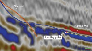
The structural model of the reservoir was based on two seismic reflectors, correlated with information from previous wells in the area (Figure 1). The objective of the new well was to penetrate the lower reflector. Log data acquired while drilling this well indicated that the landing point was positioned below the known gas-oil contact. Although the log data at the landing point did not indicate that the trajectory entered the reservoir, based on the well’s position on the seismic data, it was expected that the reservoir would be entered shortly after drilling out of the casing shoe.
The well was cased to the landing point. Then, following the original well plan, drilling proceeded with the expectation of passing through good-quality oil-bearing reservoir rock. However, it was soon discovered that the target interval – the lower sand lobe – did not correlate with the pilot and correlation wells; the logging-while-drilling (LWD) data indicated only shale.
As drilling continued, shale was encountered for a total of 590 ft (180 meters) before the decision was made to revise the status of the well to that of an appraisal.
With the lower seismic reflector not proving fruitful, the new purpose of the well was to ascertain the base, top and quality of the reservoir section indicated by the upper seismic reflector. The well was built to 94°, successfully penetrated the base and top of the upper reservoir and was then abandoned. True stratigraphic thickness (TST) of the upper reservoir was estimated to be 18 ft (5.5 meters). New information from the well was combined with the seismic and offset well data to revise the reservoir model and plan the positioning and drilling approach for a sidetrack production well.
Planning the sidetrack
The original well was landed at a true vertical depth (TVD) appropriate for accessing the lower seismic reflector. To access the new objective of the well – the upper sand lobe – it would be necessary to increase inclination above 90°. The length of the producer was restricted, however, as a section length greater than 1,345 ft (410 meters) would intersect the drainage radius of another producing well, creating production interference. A further consideration was that the length of the shale section should be minimized in order to maximize the section of reservoir sand and accommodating completion limitations.
The resulting well plan required that the inclination be built from 85° at the shoe to 94° using a preferred maximum allowable dogleg severity (DLS) of 3°/100 ft and, upon intersection with the base of the upper reservoir, quickly reduce inclination to 87° to become parallel to the reservoir surface and avoid exit through the top of the thin reservoir.
Another complexity was that an 11° change in azimuth would be required to keep the well far enough away from the closest producing well while maximizing the length of the horizontal section within the reservoir. The resulting well profile, which had the objective of achieving at least 790 ft (240 meters) within the pay zone, presented torque and drag challenges while drilling, hole-cleaning issues and completion success.
Advanced measurements for geosteering
The bottomhole assembly (BHA) used for drilling the sidetrack well included the PeriScope bed boundary mapper, a deep azimuthal electromagnetic resistivity LWD system that makes 360° deep directional measurements that can indicate the distance to and orientation of formation boundaries from the borehole. It uses a combination of tilted-coil technology and multiple frequencies and spacings. The tool is sensitive to contrasts in resistivity within a radius of investigation that varies depending on the geological environment. The resistivity contrasts can be due to changes in lithology (e.g., sand versus shale) or fluid changes, such as an oil-water contact.
During drilling operations, LWD measurements are transmitted to the surface. These symmetrized directional measurements, with maximum sensitivity to formation or fluid boundaries, make it possible to map boundaries in real time, independent of anisotropy and dip. The real-time bed mapping and curve interpretation are performed by well placement engineers using proprietary real-time geosteering software (RTGS).
The BHA also included the geoVISION imaging-while-drilling service to deliver high-resolution LWD images in real time that can identify formation structure and geological features, such as faults and fractures. It can be configured to make up to five resistivity measurements. Three azimuthally focused button electrodes offer multiple depths of investigation to permit quantification of invasion profiles. An integral cylindrical electrode delivers high-resolution lateral resistivity. At-bit resistivity measurements allow real-time coring and casing-point selection in both conductive and resistive mud environments.
Drilling the sidetrack
The LWD information was used to optimize the well trajectory in real time. Based on the new drilling model, about 460 ft (140 meters) of shale was expected between the casing shoe and the entrance to the base of the upper reservoir sand. In the event, 490 ft (150 meters) was drilled before the presence of shaly sand laminations was detected – the main indicator of the base of the reservoir predicted from measurements made in the pilot well. The laminated interval was expected to be approximately 1-meter TVD. Considering the strict well-length limitations, it was decided to build trajectory at the planned maximum DLS to minimize length in this laminated interval. The relative angle between the well and the formation layers rose close to -7°.
After crossing the laminated zones, the well entered the desired sand section; however, the interpreted results of data from the bed boundary mapper tool indicated that the well was only 8-ft (2.4-meters) TVD from the top of the reservoir, and the roof was being approached at a higher rate than expected.
The well placement team performed detailed simulations and projections to identify an adjusted well trajectory that would achieve optimum placement. It was decided to increase DLS to 5°/100 ft, which, although higher than preferred, remained within the limits of the well completion standards. Although coming close to 1.3-ft (0.4-meters) TVD of the shale roof, the well remained within the thin reservoir sand through the entire open-hole section, achieving 800 ft (245 meters) of net pay zone.
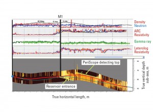
Figure 2 shows log data and bed boundary mapper results used to support geosteering decisions from casing shoe to total depth.
Post-job evaluation
Studies performed after drilling the well included a detailed review of the petrophysical and reservoir information and updates to the geological model based on the newly acquired data. Updates to the model include adjustment of the dips of structural layers, addition of subseismic faults, review of the TVD and TST of reservoirs, and alteration of the true tops and bases of formations. Key inputs to these studies include LWD measurements such as conventional logs (e.g., gamma ray, density-neutron, resistivity); images indicating apparent and true layer dips and azimuths; inversion responses and interpretations from the bed boundary mapping data; and reinterpretation of seismic data by geophysicists.
The first step is the integration of log data to identify lithologies (e.g., sand/shale content), formation fluid and net pay intervals that the well has drilled through. The sinusoidal responses interpreted from resistivity images indicated the reservoir to have an average dip of 5.5° in a 303.5° azimuth. The most representative clean sands were determined in the open-hole section and zoned consistently with the locally defined markers “alpha” and “beta.”
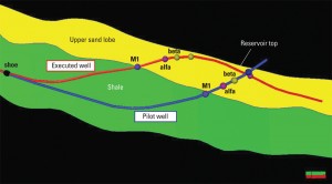
Once the lithological properties, fluid content and layer dips were determined, the next step was an analysis based on the response of the remote boundary-mapping tool. These measurements enabled the TVD position, inclination and azimuth of the top of the upper sand reservoir to be properly adjusted – a task achieved without the necessity to drill into this lithological change. Figure 3 shows a section through the updated 3D model with well positions and revised reservoir geometry surfaces and markers.
The updated model was then correlated with the seismic data to improve the understanding of the relationship between the actual surfaces and their seismic response. The knowledge gained from evaluation of new data from this well was used to benefit the planning of future wells. The bed boundary mapper and imaging-while-drilling service mentioned in this case study were both used while drilling subsequent wells in the field.
Conclusions
Factors such as thin reservoir sands, lateral lithological changes and high levels of faulting make this field a challenging environment with considerable uncertainty in the geological model. Inversion and analysis of real-time information from the bed boundary mapper tool enabled remote detection of the reservoir top and identification of the inclination tendency of the true dips of the formation layers.
Combined with precise projections, drilling expertise and proven well-placement methodologies, the proactive real-time approach avoided a second well abandonment and sidetrack, thus saving significant rig time and cost in tough drilling and reservoir conditions. The operation met the key objectives of keeping the well inside the reservoir after its first entrance from the base and achieving a net pay zone of more than 790 ft (240 meters) in the upper sand lobe.
This article is based on SPE 143752, “Successful Application of a Distance to Boundary Technology under Tough Drilling and Reservoir Conditions,” presented at the Brasil Offshore Conference and Exhibition, Macaé, Brazil, 14–17 June 2011.
PeriScope, RTGS and geoVISION are marks of Schlumberger.

