Operator finds cost-effective rotary steerable applications in Oman’s low-cost environment
By M Riyami, Petroleum Development Oman; J Edwards, E Vache, O Ojeiduma, S Johnston, Wael Darwish, Schlumberger
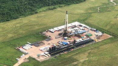
Hydrocarbon basins in the Sultanate of Oman are located in the desert, where rig rates are low. Although this is not a typical environment for sophisticated drilling systems such as rotary steerable systems (RSS), use of this technology can make business sense in some niche applications.
One application, for example, is efficient directional drilling in hard and abrasive layered formations of S-shape and J-shape profiles. Another is drilling build-ups to precise horizontal landing depths, or drilling absolutely vertical holes in wells that have long, heavy-wall liner sections that are run with inner strings and mechanical-set liner hanger packers. A dogleg can result in a liner that won’t go down yet is too heavy to retrieve.
Rotary steerables also can assist the acquisition of geological data. For example, they can be used in fractured carbonate to drill extended-reach, smooth boreholes that can be logged with un-rotatable imaging tools conveyed on drill pipe. The measure of success, and a large part of the remuneration, for the RSS used was based on imaged meterage, not drilled meterage. These wells were drilled with an inclination-hold feature that kept the trajectory as straight as possible.
Another geological application is the use of rotary steerables to accompany an azimuthal deep-reading measurement used to geosteer the well. The elimination of sliding removed blind zones, consequence of azimuthal logs, and the near-bit inclination helped the directional driller avoid over-steering when the geosteering team requested an inclination change.
This article will describe these applications, explaining how specific problems were solved with rotary steering.
Background
Drilling motors drill straight when rotating and must be slid to drill a curve. Rotary steerable systems drill both straight and curved sections while rotating. The elimination of sliding solves many drilling problems, such as maintaining the tool face orientation, slow sliding or inability to slide, poor hole cleaning when sliding, poor hole quality from rotating the motor bend and borehole tortuosity.
The rotary steerable tools used in the examples discussed here use an internal geostationary reference with everything external rotating at the drillstring rpm. The directional force on the bit in one tool is applied with a hydraulically activated pad; in the other, the bit itself is tilted. Both tools have near-bit inclino-meters, of which one was used for closed-loop steering to hold a constant inclination. This continuous inclination is available in real time, although it’s not necessary to have communication to surface for automated directional control.
Field Examples
Fast deep sidetrack with low dogleg severity
The closest directional well to the planned sidetrack was drilled with motors in a S-shaped 12 ¼-in. hole. This S-section took 43 days and 11 bit runs to drill a departure of 1,110 m, from 912 m to 3,398 m measured depth (MD). The objective of the new sidetrack was to set 7-in. casing at zero inclination and 560 m laterally displaced from the original well for a vertical 5 7/8-in. penetration of the gas-bearing formations down to 4,000 m TVD. It has previously taken approximately one month to drill the vertical section from 3,000 m to 4,000 m, so if the S-shape has high doglegs, there is a possibility of high drilling torque in the 5 7/8-in. hole and increased wear in the 7-in. casing.
To minimize the doglegs and to shorten the drilling time of the 8 3/8-in. and 5 7/8-in. sections, a point-the-bit rotary steerable system was used to drill the 8 3/8-in. S-section (Figure 1). The S-section took 10 days and one bit to drill from 1,551 m to 3,133 m MD. The ROP was comparable to offset vertical wells and considerably faster than the previous directional well. The modeled decrease in drilling torque for the vertical 5 7/8-in. section down to 4,000 m between the first 1,110-m departure wells to the rotary-steered 560-m departure well was 43%. However, the actual decrease was 63% (Figure 2). The payment metric for drilling the S-shape was calculated per meterage drilled, plus a drilling penetration rate bonus.
Fast, geometrically precise drilling
A green oil field, where development began only recently, has both a gas cap and a water contact. The vertical landing depth at the start of the horizontal laterals in the oil rim is therefore critical. The build to horizontal with these wells was more difficult than typical horizontal wells in Oman because of their greater depth — 3,200 m vertical rather than the usual 700–1,200 m — and the abrasive hard, clastic formations that occur at this depth.
The build sections of the last two wells in this horizontal development were drilled with a point-the-bit rotary drilling system that included a real-time near-bit inclination, while the first two wells were landed with drilling motors. The casing shoe-to-casing shoe time for these four wells were (in days) 18.8, 17.5, 10.5 and 7.8. In addition to improved drilling performance, a near-bit continuous inclination built into the rotary steerable tool helped with directional control. The final TVD calculated with this continuous measurement was only 40 cm off from MWD surveys.
Performance drilling
Reservoir management requirements of this green field stipulated production logging access. The wells are lifted with 4.56 series electrical submersible pumps (ESP), and the 2,000-m open-hole horizontal sections could be accessed only with a 2-in. coil. This meant the upper completion, ESP and Y-tool for 2-in. coil, must be set in 9 5/8-in. casing, which has to be set as deep as possible to minimize the vertical distance between the pump and the reservoir.
To accommodate this deep-set 9 5/8-in. casing, the 12 ¼-in. hole included a build to a tangent at 45°. This meant the hole section was taking two trips to reconfigure the bottomhole assembly (BHA). A BHA was tried that integrated a motor power section with a push-the-bit rotary steerable system that could drill the section in one run: 500 m of vertical and 500 m of build at 3.18°/30 m.
The first run showed no improvement, as bit balling necessitated a trip anyway. After bit compatibility with the formation was resolved, the next three wells drilled with the new BHA had an average drilling rate for the 12 ¼-in. section of 35 m/hr, compared with 12 m/hr before. Part of this improvement resulted from eliminating the trip, and part resulted from faster on-bottom drilling due to the combined power of the hydraulic motor and the rig rotary table (Figure 3).
Borehole verticality for running liner
Running the tapered liner in a deep reservoir beneath thick salt from 1,600 m to 4,400 m was one of the higher-risk well construction activities in this field. The liner was particularly heavy as thick casing was required to withstand hydraulic fracturing pressures. Cementation of the more recent wells were done with an inner string because it is faster and provides an option to displace the heavy drilling with lighter brine while the cement is still wet, thus avoiding the creation of a micro-annulus.
The POOH weight of the heavy liner and inner string exceeded the drilling rig maximum pull. This meant it was essential for the liner to reach total depth while running into the well, as it could not be retrieved. The use of hydraulic liner hanger setting tools was considered risky due to the high solids content of the mud.
Therefore, mechanical tools were used, requiring rotation from surface. The wells were targeting the centre of 100-m fault blocks to maximize the propped fracture wing lengths. Achieving the 25-m radius drilling target at 4,400 m often required several correction runs.
The three requirements — getting the liner to total depth on the first attempt, the ability to set the liner hanger with rotation, and hitting a 25-m target without a correction run — meant that both the 12 ¼-in. and 9 ½-in. hole sections must be perfectly vertical and smooth. In these two sections of the more recent wells, a closed-loop drilling system that automatically seeks vertical 100% of the time was used.
In the second hole section, after setting the 9 5/8-in. casing at 1,600 m, a ball-activated 9 ½-in. underreamer was run 40 m behind the 8 3/8-in. bit. This enlarged the hole to accommodate salt movement before running the liner. At the reservoir top, normally encountered at 4,000 m, 40 m of vertical 8 3/8-in. hole was drilled into the reservoir. The closed-loop drilling system was then replaced with a conventional drilling assembly to drill the remainder of the reservoir.
Real-time communication was not necessary to operate this tool. The last job was run blind, with post-drill gyro surveys confirming the vertical inclination. Figure 4 shows well trajectories drilled with and without the closed-loop rotary drilling system, and Figure 5 shows the improved hole shape in the salt. The first inner string cementation attempted in a conventionally drilled well was unsuccessful. Since then, all wells have been drilled with rotary closed-loop, with no liner-running incidents. The incentive pricing is based on dogleg severity.
Deep horizontal
A point-the-bit rotary steerable system was used in 14 of 16 runs to drill an 8 3/8-in. hole from an inclination of 75˚ to the end of the horizontal section at 4,316 m TVD. This was the first horizontal deep gas well in Oman and was designed to access the equivalent reserves of 2–3 vertical wells.
The target reservoir is hard sandstone and conglomerates, which drills with high torque and stick-slip. High regional stresses at this depth have deformed the open hole into a vertically aligned ellipse. A rotary steerable system was used to avoid sliding and the risk of stuck pipe, although sticking while sliding did occur during initial runs with a steerable turbine. These high tectonic stresses caused continuous breakouts in certain facies at the top and bottom of the hole that were clearly visible on LWD logs and which produced a high volume of cuttings.
While tripping in hole, temperature increases were limited by circulating for 30 minutes at the casing shoe and every 10 stands while running in the hole. While drilling, the circulating temperatures were regulated (staged) by monitoring the circulating temperatures transmitted in real time by the MWD tool. Whenever the temperature exceeded 130˚C, drilling was stopped and circulation was continued while working the pipe. Drilling was resumed as soon as a 10˚C drop in temperature was observed. The static reservoir temperature varies from 155˚-165˚C; however, the maximum recorded temperature was 133˚C.
Two of the 16 runs between 75˚ inclination at 4,499 m and the total depth at 4,967 m did not use a rotary steerable system: The second run was a steerable turbine that failed to build angle, and the 13th run was a conventional rotary assembly used in the horizontal hole, which dropped angle. Of the 14 rotary steerable runs, 12 were for bit changes, one was for a tool failure and one was for a logging trip. The rotary steerable system was in the hole for a total of 408 hrs and drilled 378 m, with two tools used to drill the well.
When the point-the-bit system was not required to steer the bit, offset was not kept at a constant tool face; instead it was rotated to cancel the side cutting. The steering ratio is the fraction of time the bit offset is kept at a constant tool face. In the build section from 75˚ to 90˚, corresponding to 4,499 m to 4,710 m, the average steering ratio was 54%. This resulted in a dogleg of 3.73˚/30 m. All external components of the tool rotated with the drill string rpm, regardless of whether the bit was steering.
Using the wipe image logs recorded with LWD, which revealed a change in structural dip, the well plan was changed twice while drilling. The resistivity and density images also detected natural fractures. No other logs were recorded as it was considered too risky to run drill pipe conveyed wireline logging. By the end of the well, there was 1,890 m of open hole, with the first portion open for 88 days (Figure 7).
Acquiring wireline images
The objective was to acquire resistivity images of the naturally fractured formation with a wireline logging tool in extended-reach horizontal appraisal wells.
Fracture density is one of the critical parameters needed to establish the viability of oil recovery techniques being considered for these shallow carbonate reservoirs containing heavy oil.
The fragile imaging tool could not be rotated, so drillpipe conveyed logging (TLC) was used to slide the tool into the well. The hold-up depth of a slid drillpipe is determined by several variables, including wellbore tortuosity. Non-conductive friction reducers like Radia Green couldn’t be used because it spoils the resistivity image. TLC logging was attempted in several motor-drilled appraisal wells; they were not all successfully logged.
Torque and drag modeling on planned trajectories showed that a rotary steerable drilling system, when used in inclination hold, can be tripped 14% deeper than a drilling system in holes that aren’t perfectly straight. The tortuosity from the motor-created micro-doglegs was assumed to be equivalent to a snaking hole with a continuous curvature of 1°/10 m. Based on this result, and the failure to complete the logging of the previous well, a rotary steerable system was used instead of a motor in the next three wells.
Figure 6 shows the planned, drilled and logged horizontal drain holes of nine extended-reach wells with measured/vertical depth ratios from 2.2 to 4.2. The logging success with rotary steerables was 3/3, whereas for motors it was 2/6. The RSS also drilled faster. This service was run under an incentive contract, with the meterage rate a function of the successfully logged, not drilled, interval.
Improved LWD images
In horizontal extended-reach wells, it’s possible to drill with a RSS beyond the ability to slide the drillpipe. This may mean the deepest section of the well cannot be logged with TLC because the conveyance is all sliding. In this case, the deepest section can only be logged with LWD.
Fracture characterization was critical to the reservoir drainage mechanism of this field, so it was necessary that the resistivity image recorded with a LWD collar at the end of the well was of the best quality possible — perhaps approaching the resolution of wireline images recorded in the shallower section. This would only be possible if the hole is very close to gauge because, unlike the wireline tool, LWD imaging sensors are mounted on fixed-diameter stabilizers, which makes the image sensitive to any hole enlargement.
LWD resistivity images acquired while drilling with a rotary steerable system were found to be superior to images acquired with the same imaging tool while drilling with a motor in the same formation in a nearby field. This improvement is thought to be a consequence of the RSS drilling a smoother, closer-gauge hole than a motor; there is no spiraling from the rotating motor bend. Figure 7 shows LWD images compared with wireline images in the rotary-steered well. The rotary steerable system solved both problems — extending the length of the horizontal section and facilitating the acquisition of acceptable images.
Geosteering with azimuthal measurements
Geosteering in a 3-m-thick reservoir layer with an azimuthal deep-reading resistivity is complemented by a drilling system that always rotates. This eliminates the blank zones that result from sliding with a drilling motor because azimuthal measurements do not work when sliding. It is useful to retain the full geosteering functionality when drilling curves to avoid the upper or lower boundary, especially if this involves a close approach. The rotary steerable system includes a continuous near-bit inclination 2.7 m from the bit and a gamma ray sensor 2.5 m from the bit. This real-time feedback available to the directional driller while drilling the curves helped to control the dogleg.
An example of this is shown in Figures 8 and 9. When the geosteering tool rotates, the data transmitted to surface is used to calculate the distance to the boundaries above and below the wellbore in real time. When approaching a boundary, the wellbore trajectory is altered to avoid exiting the reservoir.
Because the well in this example was drilled with a rotary steerable system, the distance to boundary could be monitored throughout the steered interval. If this well had been drilled with a motor, this geological data would not have been available during the slides. To illustrate how this geosteering operation would have looked if drilled with a motor, all the steered intervals are shown as blanks in the geological section. Geosteering with these blanks would have increased the risk of drilling an unintentional exit from the reservoir. The incentive pricing for a portion of the geosteering work was based on close distance to boundary, with a penalty for each exit not related to a fault.
Conclusions
Rotary steerable systems can solve specific drilling requirements, such as performance drilling, a smooth hole for image logging, a perfectly vertical hole for running a difficult casing, and improved geosteering when using azimuthal measurements. Rotary steerable systems are well suited for the increase of directional drilling in deep and very shallow reservoirs in Oman.
Acknowledgements: The authors would like to thank the Ministry of Oil & Gas, Petroleum Development Oman and Schlumberger for authorizing publication of this work.
References
1. J. Edwards, Schlumberger, “Applications of Rotary Steerable Systems in Oman,” Oman First Oil & Gas Workshop, Muscat, Oman, 16–17 April 2007.
2. S. Daveridge et al, Petroleum Development Oman, “An Innovative Business Model to Leverage Innovative Well-Placement Technology,” OTC-17591-PP, Offshore
Technology Conference, Houston, 2–5 May 2005.
This article is based on a presentation at the IADC World Drilling 2008 Conference & Exhibition, 11-12 June, Berlin, Germany.