Merged multilaterals system cuts time, risk
Combining whipstock, sealbore diverter into one downhole assembly reduces rig, open-hole exposure times
By Christopher Guidry, Charles Pleasants and Joseph Sheehan, Baker Hughes

Inherent risks in component alignment and open-hole exposure time during conventional multilateral casing junction operations spurred the need for an innovative well completions method. The combining and advancement of known casing exit and multilateral technologies provided the solution to this junction completion reliability concern. Concurrent development and enhancements of milling bottomhole assemblies (BHAs) supported the effort to improve casing exit window lengths, a critical initial aspect for successful intervention and completion processes.
This article explains the benefits that may be realized by integrating a combination whipstock and sealbore diverter system into multilateral junction completions.
Casing Exits
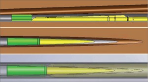
Prior to the progression of wellbore intervention technology, specifically at the advent of casing exit technology, an unintended obstruction in a cased wellbore or an improper trajectory of a cased wellbore into a reservoir would necessitate that another well be spudded to potentially reach the intended payzone. In extreme cases, if the option of drilling another well into the desired reservoir was not available, the reservoir would ultimately be unreachable. The ability to exit a well’s main-bore casing was born from the need to reach a desired reservoir zone without drilling an additional main bore and well.
Today the reasons for employing casing exit technology are vast, other than circumnavigating unintended obstructions. Performing casing exits for subsequent completion of multilateral junctions can reduce the number of slots on platforms, reduce the surface locations in remote areas, reduce drilling and completion costs, and minimize the environmental impact of drilling, completion and production. In short, casing exit technology has fulfilled the need to reach multiple production zones from a single well’s main bore.
The primary methods of creating an exit in casing include section milling and window milling. As the name suggests, section milling involves milling away at a predetermined well depth the complete circumference of a length-section of wellbore casing or liner. The section milling method of exiting casing can be completed using available equipment. Also appropriately named, window milling pertains to milling at a predetermined well depth a generally elliptically shaped opening in a cased or lined wellbore.
The window milling method of exiting casing can be completed using milling BHAs in conjunction with whipstock system equipment. An advantage of window milling over section milling is that less cuttings debris material needs to be circulated out of the well during the first method. For the same length of either a milled section or a milled window, much less metal cuttings need to be removed during a window milling procedure than during a section milling procedure.

However, of greater criticality when using the window milling casing exit method is the combined axial and rotational location of the milled window. This positioning is significant because the trajectory of subsequently run drilling BHAs, and thus the trajectory of the lateral wellbore, depends on the initial positioning of the whipstock. Therefore, while whipstock systems can provide a means to efficiently exit casing and provide a window through which it is suitable to run drilling BHAs, liners and completion equipment, the initial set position of the whipstock also significantly affects the critical position and direction of the subsequently milled window, the trajectory of the subsequently run drilling BHA, and the course of the lateral wellbore.
Multilaterals

Multilateral technology creates multiple wellbores that extend laterally from a well’s initially spudded main wellbore. The creation of a cased lateral wellbore starts by completing a main wellbore casing exit operation. Then the junction between the main wellbore and the lateral wellbore can be completed.
Multilateral formation junction completion systems of varying support and pressure integrity levels are available, and the choice of which multilateral systems to use depends on the desired complexity of the formation junction between the main wellbore and the lateral wellbore. Some systems provide flexible completion options to allow the system to be completed as a dual or commingled completion with selective access for production or injection wells. Similar systems consisting of a main wellbore and one or more cased branches are designed to drift through a smaller casing size and, using a downhole reforming process, achieve a full-size, hydraulically sealed multilateral junction.
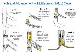
The most common multilateral systems provide a junction at the casing exit that allows completion of both the main wellbore and the lateral wellbore and can allow selective re-entry into either wellbore. When the requirement is for the completed junction to be made up of a cased and cemented main wellbore and lateral wellbore, and pressure isolation is to be achieved with completion equipment, a sealbore diverter is used to divert drilling and/or completion assemblies into the open-hole lateral wellbore.
In a traditional multilateral operation sequence, the multilateral sealbore diverter must be run in hole and correctly axially and rotationally positioned only after first milling a window exit and retrieving the used whipstock, but before running and setting the manufactured multilateral casing junction system.
TAML CODE
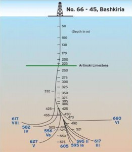
The first multilateral well with horizontal sections was drilled in the US in the late 1930s, albeit it was completed using men drilling in horizontal radial patterns from the bottom of an 8-ft diameter hole. The world’s first true multilateral well was drilled by Alexander Mikhailovich Grigoryan in the Ishimbainefti Field in Bashkiria, USSR (today’s Bashkortostan, Russia).
In 1953, Mr Grigoryan drilled Well 66/45 using only turbodrills, without rotating drillstrings, cement bridges or whipstocks. The well had nine branches, each extending 262 ½ ft to 984 ft. Because of his pioneering efforts through the next three decades, the drilling of multilateral wells in the US flourished in the 1980s. It was not until the 1990s that “modern” multilateral wellbore junction systems began to be built with features and capabilities beyond those of only a simple sidetracked well.
The progression of multilateral technology during the 1990s led to the formation of an operators’ group to share experiences, establish an informal network of contacts and provide a more unified direction for the development of multilateral technology. In 1997, at a kick-off meeting in Aberdeen, Scotland, Technical Advancement of Multilaterals (TAML), a group formed as a joint industry project, was started. TAML is best known for developing a multilateral classification or ranking system that serves as the industry standard for describing multilateral wells.
Although TAML was originally formed as an operators’ group, membership eventually grew to include service companies and academia. With input from TAML and the effort of service companies to provide improved tools, the evolution of multilateral technology has continued.
Casing Exit and Junction Installation Sequence
Recently, with the developmental progression of Level 5 multilaterals, especially those designed for high-pressure reservoirs, manufactured casing junctions with high burst and collapse ratings have become the customary installation. Likewise, junctions consisting of a main wellbore and two cased lateral wellbore legs have become the standard for Level 5 multilaterals. Typical systems of this sort use sealbore diverters, deployed and retrieved using drill pipe runs, to gain access to the required wellbore leg for subsequent completion operations. Positive diverter orientation can be accomplished by mating it with an orientation lug in the multilateral junction system.
Flexible completion options allow some casing junction systems to be completed as a dual or commingled completion with multilateral-sealbore-diverter supplied selective access in production or injection wells. In a typical operation in which a sealbore diverter is used, a standard anchor/packer and whipstock are deployed downhole, oriented and set in place. After the BHA is in place, the casing exit window can be created. This is most often completed with a milling BHA that is deployed downhole as part of the complete BHA so that the whipstock can be set and the casing exit can be created in one downhole trip. An open-hole lateral section is then drilled through the casing exit window to the desired total depth.

After all associated casing exit operations have been completed, including all hole reaming and cleaning procedures, the sealbore diverter is run in hole, aligned and installed into the anchor/packer above the existing main-bore liner in the casing. With the sealbore diverter in place, the manufactured casing junction can be deployed. This assembly is run through the wellbore casing until the liner or screens that are run below the casing junction’s lateral leg are diverted through the casing exit window and into the open-hole lateral wellbore.

This assembly run-in process continues until the main wellbore leg of the casing junction lands within the sealbore diverter previously installed in the anchor/packer. Pressure integrity of the multilateral casing junction is then achieved. The conventional casing exit and casing junction installation sequence steps can be summarized as:
- Install whipstock into the well’s main bore using an anchor/packer orienting profile as a depth and orientation base.
- Using a milling BHA and whipstock, generate a casing exit window and a short open-hole rathole.
- Drill the open-hole lateral section to the desired depth.
- Retrieve the used whipstock.
- Run wellbore clean-up tools to prepare the orienting profile for the sealbore diverter installation.
- On surface, orient the sealbore diverter face to match the orientation of the whipstock scoop face.
- On a running tool, run the sealbore diverter into the well.
- Land and latch the sealbore diverter into the anchored orientation profile.
- Return the running tool back to surface.
- Deploy downhole the manufactured casing junction and install it into the sealbore diverter.
Reliability, Risk Concerns
Reliability and risk mitigation are two important aspects of modern well design. The first step in risk mitigation is the identification of design or system limitations. With regards to casing exit and multilateral technology, one risk is the inability to drift tools out into the open-hole lateral leg. The limitations associated with creating a casing exit and installing a ramp or kick-off feature to ensure that equipment can be drifted into an open-hole lateral leg off of a cased main bore can be characterized in two parts – axial location and rotational orientation.
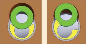
The axial positioning of the ramp (diverter) feature is important because if it is positioned too high or too low relative to the casing exit, the available drift into the lateral leg may be limited. When the kick-off ramp is positioned too high relative to the casing exit (Figure 1), the available drift area may be limited by the distance between the ramp feature and the open-hole lateral.
If the kick-off ramp is positioned too low (Figure 2), the ability to enter the lateral leg may be hindered due to the width of the casing exit window at the location of the kick-off ramp. Additionally, if the kick-off ramp is not exactly rotationally aligned to the casing exit window (Figure 3), there may be drift limitations due to the kick-off ramp and the casing exit or open-hole lateral choking off drift access to the lateral.
Rotational orientation and axial positioning are not mutually exclusive parameters, and the combination of the two must be considered when discussing the available drift access into the lateral. One way to mitigate the risks is to perform drift testing to determine operating parameters linked to the different components in the system. However, the larger the drift diameter required to enter into the open-hole lateral, the smaller the window of opportunity for positioning the kick-off ramp both axially and rotationally.
Another potential issue with well completions is the possibility of lateral open-hole collapse, in which the open-hole lateral may fully collapse or the drift in the lateral may be reduced. Typically, once the open-hole lateral is drilled, it is desirable to install the lateral liner in the shortest time possible. As wells get deeper and multilateral junctions are installed deeper in wellbores, the time between when the open-hole lateral is drilled, when the drilling BHAs are retrieved and when the completion equipment is installed will only increase as trip times to reach total depth will increase.
Although the aforementioned risk issues can and have been mitigated to achieve dependable multilateral casing junctions, a more efficient means of mitigating these issues was desired. The combining of existing casing exit technology and multilateral technology proved to be the solution that provided the greatest benefits.
Casing Exit and Junction Installation
The concern regarding sealbore diverter axial and rotational orientation and placement was the impetus behind efforts to create a system feature whereby a whipstock sealbore diverter at the outset of a casing exit operation would inevitably be positioned correctly relative to the casing exit window. By creating such a system, a means to establish a known fixed location for a sealbore diverter relative to the casing exit window would be accomplished.
By merging casing exit and multilateral technologies, a combination whipstock and sealbore diverter system was developed that would reduce casing junction installation risks by eliminating the uncertainties prevalent when installing an independent sealbore diverter.
A combination whipstock and sealbore diverter system was built, qualified and field tested. An advanced milling BHA analysis program was concurrently used to ensure the desired performance of the milling BHA used to create the casing exit window. Use of this analysis program led to the development of a new geometry milling BHA to maximize window length to improve ingress and egress of subsequently run steerable drilling BHAs.
Designing a milling system with balanced contact load characteristics was important for use with this new combination whipstock and sealbore diverter system. The balanced milling assembly was designed so that its stiffness allowed for a long window, yet its flexibility allowed for the milling BHA to build angle and travel away from the anchor in the main wellbore once it traversed past the transition point. Using the combination system, a complete window is normally accomplished in one drill pipe round trip; the starting cut is made, the window is milled and a pilot hole is drilled for the subsequently run drilling BHA.
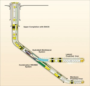
Once the window is completed and the open-hole lateral leg section is drilled, the upper whipstock portion of the assembly is removed, and the manufactured casing junction is installed in the whipstock sealbore diverter that remains in its originally set downhole position.
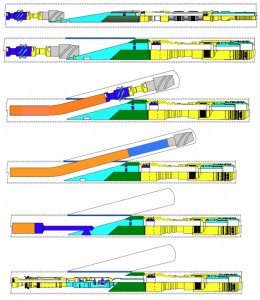
Essentially, the casing exit is generated and the sealbore diverter is installed in one run, then the run to set the junctions can follow. The operator will benefit from the reduction in lateral leg open-hole exposure time, as well as in the reduction in the time required to install the junction. Additionally, orientation concerns tied to the installation of the sealbore diverter will be minimized.
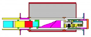
A model of a combination whipstock and sealbore diverter is shown in Figure 4. The casing exit and multilateral casing junction installation sequence steps can be summarized as:
- Install a combination whipstock and sealbore diverter into the well’s main bore using an anchor packer orienting profile as a depth and orientation base.
- Using a milling BHA, generate a casing exit window and a short open-hole rathole.
- Drill the open-hole lateral section to the desired depth.
- Retrieve only the used top whipstock portion of the combination whipstock and sealbore diverter, leaving the sealbore diverter portion anchored downhole.
- Run clean-up tools to prepare the whipstock sealbore diverter for the manufactured casing junction installation.
- Deploy downhole the manufactured casing junction and install it into the whipstock sealbore diverter.
Reliability, Risk Mitigation Improvement
In addition to the inherent financial benefit of reducing installation trips by combining the whipstock and sealbore diverter systems, there is the benefit to be able to manage risks associated with this type of multilateral installation. As stated earlier, one possible risk is the inability to drift tools out into the open-hole lateral leg due to the difficulty in positioning the kick-off ramp axially and rotationally with respect to the casing exit window.
By combining the casing exit whipstock system and the sealbore diverter kick-off ramp, this issue is eliminated. Once the whipstock is retrieved, by the design of the system, the whipstock sealbore diverter remains optimally positioned with respect to the casing exit window, allowing maximum drift access to the lateral.
The removal of the trip to install the sealbore diverter of the system has the added benefit of reducing the operational risks linked to lateral open-hole exposure time. In the two-trip method of milling a casing exit, drilling the open-hole lateral, retrieving the whipstock, running the sealbore diverter, and installing the lateral liner and junction, the time between when the lateral open-hole is drilled to when the lateral liner is installed can be significant. By combining the whipstock and sealbore diverter, once the whipstock portion is retrieved, the lateral liner and junction can be installed.
Maximizing Casing Exit Window Length
Casing exit milling systems and BHAs have progressed significantly over the years, from initially requiring two trips to mill a window to today’s one-trip systems. Earlier systems would combine the setting of the whipstock and bottom-set anchor with a starting mill BHA, which would create a starting cut or ledge. This was accomplished by the tapered nose of the starter mill progressing axially along the lug of the whipstock for approximately 2 ft, which created a radial cut in the casing. The second trip to complete the window would have a more conventional BHA consisting of a window mill, a lower watermelon mill and an upper watermelon mill.
This BHA would engage the ledge in the casing created by the first run and elongate the window for future passage of a formation drilling BHA. This method was highly successful.
The growing need to reduce rig trip times increased the demand for one-trip casing exit systems. Early one-trip systems consisted of a “tapered” milling system, a three-mill system with an under-gauge window mill, a lower watermelon mill, a flex joint and a full-gauge upper watermelon mill. One drawback was that only one of the three mills, the upper watermelon mill, was designed to mill a hole achieving a near casing drift diameter.
This milling BHA configuration required that the entire length of the milling BHA be totally traversed across the whipstock scoop to ensure that a full-gauge window was generated.
Ultimately, full-gauge mills were used in three-mill casing exit systems. However, until finite element analysis (FEA) software became available to analyze these BHAs in detail, extensive testing with variances in mill diameters and spacing was necessary to confirm performance and reliability. With the advent of FEA software, load and fatigue estimation became possible by changing mill diameters, mill geometry and spacing. The above was employed in the milling BHA design for this combination whipstock and sealbore diverter application.
The milling BHA used with the original combination whipstock and sealbore diverter system consists of a full-gauge window mill, full-gauge ball mill, flex joint and full-gauge upper watermelon mill. The spacing of the mills allows the side load to be maximized where it is needed most, at the location where the window mill completely exits the casing. It is at this point that the casing is no longer providing a restraining force keeping the window mill against the ramp of the whipstock. The milling BHA was designed so that it creates an outward force on the window mill as it leaves the ramp of the whipstock.
This allows the BHA to build angle as it traverses the formation. Another distinct advantage of the FEA is the ability to design a milling BHA that generates a longer and straighter window that extends above the top of the whipstock. This is important due to the increased length and rigidity of the oil and gas industry’s directional drilling BHAs.
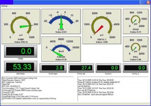
Figure 5 plots the side force versus the distance of bit from kick-off point for a contemporary milling BHA to be used in conjunction with a combination whipstock and sealbore diverter system.
To hasten the development process, the milling BHA was developed concurrent to the development of the combination whipstock and sealbore diverter system. This was accomplished by vertical test well qualification of the designed milling BHA, using a whipstock of the same length and angle ramp as that used in similar whipstock casing exit systems. The entire combination whipstock and sealbore diverter system, including the milling BHA, was then qualified on a horizontal test skid to more closely simulate actual downhole North Sea well geometries.
Qualification in the vertical test well was successful and resulted in a long and straight window. The top of the window extended approximately 0.62 ft above the top of the whipstock.
Combination System Qualification
The client desired horizontal qualification of the combination whipstock and sealbore diverter system, including the milling BHA, to simulate actual downhole North Sea well geometries. Horizontal test facilities are not in abundance, in particular of the size necessary to qualify a 9 5/8-in. casing exit system. Following discussions between a UK operations group and a Houston technology group, it was decided to perform a major retrofit of an existing through-tubing horizontal test skid in Aberdeen.
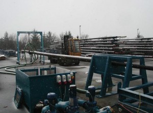
A horizontal test facility was overhauled. A 100-ft-long trolley bed runs along the back of the test area, with an anchor frame at the end of which the test casing is connected by flange. Along the top of this frame runs the tool string support, main drive, hydraulic ram and anchor trolleys. The anchor trolley is the only component directly affixed to the bed and can be pinned at various locations along its length. The hydraulic rams are arranged on top and opposite each other, with one ram connected to the anchor trolley and the other to the main drive trolley through a load pin.
This allows a total movement equivalent to the sum of both cylinders while taking up the least amount of length. The hydraulic cylinders are operated through a standard load-holding spool-valve system and offer the operator control over both the speed of travel and force. By “crabbing” the cylinder trolley and adjusting the anchor trolley, the main drive can be moved over the length of the bed.
The main drive trolley has all the major rotary components affixed to it and provides the anchor point for the torsion and axial loading from the tool string. Test fluid is supplied from the main holding tank to the triplex pump by a low-pressure electric centrifugal pump and then through a flexible hose to the fluid thrust swivel. The fluid is then returned from various points on the test fixture and anchor frame through flexible pipe to the returns tank. At the returns tank, the fluid passes over a weir and filter system to remove cuttings and other debris before being pumped back to the holding tank. The holding tank is fitted with a pumped circulation system to keep any additives in solution should it be necessary to use them with the test fluid.
The site has easy access to cranes and forklift trucks. Compressed air is supplied by a dedicated compressor, and the main drive and fluid-handling equipment is powered by a standalone diesel generator..
Data Acquisition System
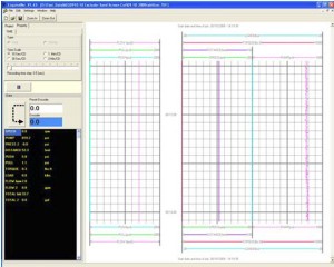
The test area uses a 10-channel data-acquisition system with custom-designed software interface. This system allows the recording and display of the various inputs, as well as project summary information and time-stamped text comments that can be entered during testing. The data recording rate can be varied from 0.1 sec to 10 min per sample.
Combination System Qualification Test Results
It was necessary to build the horizontal test facility before the casing exit qualification test of the combination whipstock and sealbore diverter system could be performed horizontally. The objective of the qualification test was to mill a casing exit window through C-110 casing using an 8.50-in. outside diameter (OD) mill/drill formation mill with the newly designed milling BHA.
An 8.38-in. OD combination whipstock and sealbore diverter system was anchored inside a section of 9 5/8-in.-OD casing that had been placed inside a 36-in.-OD internally cemented fixture. The complete fixture was mounted on the horizontal test skid.
After completing the casing exit, the open-hole lateral leg was reamed out to the bottom of the 60-ft long fixture. The milling BHA was removed from the casing, then a mockup drilling BHA was run through the window to confirm that there were no issues with ingress/egress of the drilling BHA through the milled window and drilled lateral. The whipstock (top) portion of the combination whipstock and sealbore diverter was then retrieved using a hook-style lug retrieving tool.

To simulate a contingency for rectifying an open-hole collapse scenario, a guidestock was run in hole and joined to the remaining sealbore diverter. This action would allow a drilling BHA to again traverse the window in the event of open-hole collapse. The guidestock was then retrieved, and the hole was cleaned in preparation for the subsequent 7 in. x 4 in. x 4 in. multilateral junction test. The sequence of casing exit qualification test steps is summarized as:
- The milling BHA was pushed inside the test fixture and aligned with the casing fixture. The whipstock rotational orientation was set with whipstock scoop facing 33° left of high casing side.
- To ensure that the anchor was latched in the profile sub, a set-down load of 20,000 lbs was applied and followed with a pickup load of 11,000 lbs. The load was then released.
- To shear the shear bolt that attaches the milling BHA to the combination whipstock and sealbore diverter system, a set-down load of 25,000 lbs was applied.
- The milling BHA was pulled up-hole about 2 ft from top of the whipstock. Circulation pumps were started, and pump rate was held between 3 to 6 bbl/min and adjusted as needed.
- Rotation of the BHA was initiated and slowly increased to 90-130 rpm. The window was milled using a set-down load that varied from 1,000 to 13,000 lbs.
- After completing the casing exit, the simulated open-hole lateral leg was drilled to the bottom of the test fixture.
- An 8 ½-in. OD simulated stiff drilling BHA was made up and run inside the fixture to drift the casing exit window. With only 13,000 to 20,000 lbs of drag force, the mock drilling BHA successfully traversed the casing exit window.
- After the mock drilling BHA was removed from the test fixture, a hook-style lug-retrieving tool was used to latch and retrieve the whipstock. To release the whipstock, a pull load of 68,000 lbs was required to release the whipstock collet.
- The whipstock sealbore diverter was left in place.
- To check for ease of drifting a swell packer, a swell packer BHA was run through the fixture’s casing exit window to the bottom of the fixture’s open-hole lateral. A 2,000- to 3,000-lb push load and a 3,000- to 4,000-lb pull load were respectively required to move the swell packer through the window and lateral, to the bottom of the fixture, and back up again.
- The guidestock was run in hole and the guidestock collet was latched into the diverter housing by applying a 22,000-lb push load.
- A 26,000-lb push load was required to shear the shear bolt and release the milling BHA from the guidestock. Steps 4 through 6 were repeated to ream the window.
- The 8 1/2-in.-OD stiff simulated drilling BHA was again made up and run to drift the casing exit window. With only 3,600 to 4,500 lbs of drag force, the mock drilling BHA successfully traversed the casing exit window.
- After the mock drilling BHA was removed from the test fixture, the hook-style lug retrieving tool was used to latch/ retrieve the guidestock. To release the guidestock, a pull load of 56,000 lbs was required to release the guidestock collet.
- The fixture’s casing exit window and open-hole lateral hole was cleaned in preparation for the subsequent multilateral junction test.
Qualification Test Conclusions

The positioning and orienting of the milling BHA and anchor was completed without incident. Milling of the horizontal casing exit window was comparable to that of past windows milled in the vertical condition with normal mill wear. The stiff drilling BHA was run through the window and drifted with no difficulties encountered. The whipstock collet released within the normal load range; however, the 68,000-lb drag load to pull free was very near the rated 80,000-lb pullout load of the collet in the bottom anchor.
The swell packer was run across the whipstock sealbore diverter and casing exit window with no problems. Both the retrieval of the guidestock using the hook-style lug retrieving tool and the retrieval of the whipstock sealbore diverter using a multilateral running/retrieving tool were successful. The combination whipstock and sealbore diverter system was qualified and ready for field trials.
Case History
A field trial of the combination whipstock and sealbore diverter system was completed in Q2 2010. The operation occurred in the Norwegian Sea 170 km off the Norwegian coast. The main bore completion used one-trip stage cementing to isolate the gas cap and a pre-drilled liner with swell packers for zonal isolation. A liner hanger packer with integral orientation profiles was run as part of the main bore completion. The orientation profiles in the liner hanger packer were used for aligning the combination whipstock and sealbore diverter system so that the casing exit would be milled at the desired orientation.
The combination system was installed and the casing exit window was completed. The open-hole lateral was then drilled to total depth. The whipstock portion of the system was then retrieved, leaving the sealbore diverter in place. Before running the lateral completion and multilateral junction, a clean-out trip was made to ensure that the whipstock sealbore diverter was clear of any debris.
The lateral completion, consisting of pre-drilled liner, swell packers and the junction with the main bore production diverter and a pre-installed polished-bore receptacle, was run in hole. A bullnose on the end of the liner completion was used to ensure that the lateral completion diverted off of the whipstock sealbore diverter into the open-hole lateral. The lateral completion was run in, and the junction was landed and sealed in the whipstock sealbore diverter. The liner hanger packer on top of the multilateral junction was then set.
The well was cleaned using a wellbore filter, casing scraper and other accessories. The well was displaced to brine prior to installation of the downhole instrumentation and control system (DIACS). The DIACS upper completion, with top completion seal assembly, DIACS valves, production packer and gas lift equipment, was installed and landed with a tubing hanger.
Conclusion
From the results of horizontal skid and field qualification testing, it is evident that reliability enhancements to wellbore completion projects can be realized. System testing confirmed that proper orientation of the combination whipstock and sealbore diverter system could be established with an anchor/packer orienting profile and that the function of the whipstock sealbore diverter was equivalent to the multilateral sealbore diverter. It was also confirmed that a casing exit window of sufficient length for subsequently run long and stiff drilling BHAs could be replicated with the concurrently designed new milling BHA.
By uniting casing exit, sealbore diverter and multilateral casing junction technologies into a more reliable, less risky, cost-effective system, apprehensions regarding lateral and rotational alignment of complementary intervention-completion equipment can be addressed. Additionally, remedial roundtrips due to open-hole collapse will be reduced because of the inherent trip/time saving aspects of the combination system.
Comparisons of existing wellbore intervention casing exit systems to the new combination system demonstrate the reduced risks and the predicted trip/time savings of the latter.
The combination whipstock and sealbore diverter system has proven that it can fulfill this improvement requirement successfully. The original primary design requirement for this combination system was that the sealbore diverter be deployed and installed as part of the whipstock casing exit assembly. This allows the whipstock to be retrieved while leaving the sealbore diverter installed in the well. Qualification of this system proved that the associated innovative casing exit and multilateral casing junction installation sequence is a viable new multilateral wellbore completion method.
This article is based on SPE/IADC 140274, “Merging Multilateral and Casing Exit Technologies to Increase Wellbore Junction Reliability by Reducing Rig and Openhole Exposure Times,” SPE/IADC Drilling Conference & Exhibition, Amsterdam, 1-3 March 2011.
Acknowledgments
The authors wish to thank the management of Baker Hughes, Inc. for its support and permission to publish this paper. The authors would also like to express special gratitude to Baker Hughes-Aberdeen-Kirkhill personnel and to Baker Hughes-Norway personnel for their tireless hours spent on the modification to the Kirkhill horizontal test facility and on the qualification of the equipment reviewed in this SPE/IADC paper.
References
Bonner, J., “Multilateral technology then and now,” Hart’s E&P, August 1, 2007.
DeGeare, J,. The Guide to Oilwell Fishing Operations. Burlington, MA, Gulf Professional Publishing, 2003.
Moritis, G., “TAML refocuses on educating industry on multilaterals,” The Oil and Gas Journal, Feb. 2003.

