LRRS treads fine line within drilling window
Low riser return system adjusts riser mud level for enhanced pressure control in wells with narrow operating margins
By Kristin Falk, Borre Fossli, Cathrine Lagerberg, Ocean Riser Systems; Arne Handal, Sigbjørn Sangesland, Norwegian University of Science & Technology
The low riser return system (LRRS) is a method for managing wellbore pressures during offshore drilling operations. It works by adjusting the mud level in the marine riser by returning mud and cuttings to surface through a subsea pump in a separate conduit. It is a single mud gradient, open managed pressure drilling (MPD) system designed for subsea drilling.
The LRRS can be used in two application modes. The first has a full riser during static conditions using conventional mud weights and the capability to lower the fluid level to compensate for the equivalent circulating density (ECD) effect during circulation and drilling as needed. With this technique, conventional well control procedures are used. The second technique involves using higher-than-conventional mud weights and lower fluid levels for both static and dynamic (circulating) operations. Modified well control procedures must be used with this technique.
Both methods improve safety margins, allow for better pressure control and increase efficiency for most well operations.
This article focuses on the well control issues of drilling with a partially evacuated marine drilling riser. Two case examples using data from deepwater US Gulf of Mexico (GOM) wells illustrate how the LRRS gradient fits inside the drilling window.
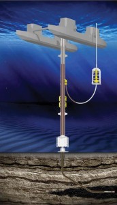
Low riser return system
By using the LRRS to manage the height of mud in the riser at any one time (level adjustment), the annular and bottomhole pressures (BHPs) can be proactively managed. The system can be used for purely ECD compensation purposes (conventional mud weight) or in combination with a heavier-than-conventional mud weight and lower static level in the riser.
The benefit of using a conventional mud weight is that conventional well control procedures can be used. In static conditions, the riser is full to the flowline outlet or just below. As circulation commences, the rig pumps will be ramped up slowly. The circulation up the annulus will increase the BHP, and the ECD component builds up. The level will then be lowered using the subsea pump, and the control system will continuously adjust the level of mud in the riser to compensate for the increasing BHP due to the ECD effect.
Controlling rates of the rig pumps and the subsea lift pump will keep the BHP or any fixed point in the wellbore near constant and within the desired pore and fracture pressure window. This method can be used to drill the longer hole sections in wells with narrow operational mud windows, such as in depleted formations, and to avoid losses during drilling, cementing and completion.
The full effect of the LRRS technology will be achieved only by increasing the mud weight and using a lower-than-conventional static riser level. In most cases, this allows for managing higher and lower wellbore pressure requirements (both planned and unplanned) by adjusting the fluid level. This gives a higher degree of operational maneuverability to operate in a better balance between pore pressure and fracture pressure and can be applied to all subsea drilling operations after the marine drilling riser has been installed. Normally, the relative effects of the LRRS will be inversely proportional to well depth from the rotary kelly bushing (RKB).
Thus, the potential benefits and effects of using higher-than-conventional mud weights are more significant in the upper part of the well. This makes the LRRS particularly beneficial for deepwater drilling for reasons related to well control and well integrity:
1. Improved safety margins while drilling (larger margin toward kick or loss);
2. Improved kick and loss detection;
3. Improved kick margins;
4. More likely to achieve a riser margin;
5. Possible to circulate out a kick without closing a BOP element;
6. Partially or completely self-regulating with respect to inflow and kicks;
7. Improved cementing operations, which improves zonal isolation; and
8. Barrier and well integrity improvements.
Drilling with heavier mud weights and a partially evacuated marine drilling riser requires new well control procedures and equipment to manage hydrocarbon influxes.
LRRS applications
LRRS is designed to control and manage well pressures. The system has two parameters that can be changed to obtain the desired pressure in the wellbore, namely the mud density (gradient) and the annulus/riser mud level.
Its main applications are related to wells with challenging pressure regimes, such as:
• High pressure combined with a narrow drilling window in deep and medium-deep water. For such cases, a heavier mud combined with a low mud level will give a better fit to the drilling window. The benefit is also useful for shallow water if there are shallow hazards, such as shallow gas, shallow-water flow or mud volcanoes;
• High ECD combined with narrow drilling window. In sections with narrow margins, lowering the mud level can compensate for the increased ECD. This is the case both during drilling and cementing. Surge and swab related to tripping can also be accounted for. One example is highly depleted reservoirs;
• Low formation pressures. Reducing the total static head by lowering the level can allow the use of a better drilling mud that might be too heavy for conventional drilling; and
• Uncertain formation pressure and strength or drilling salt sections.
The system
Two versions of the LRRS have been designated: LRRS Light and LRRS Heavy. LRRS Light is used for ECD compensation and improved kick loss detection; it uses conventional well control procedures and requires minimal incremental rig integration. LRRS Heavy uses a heavier-than-conventional mud, which would, in most cases, fracture the formation if the mud level were brought to surface. This system is dependent on LRRS well control procedures, including implementation of a subsea drilling choke with some additional equipment and well control training.
Figure 1 illustrates LRRS connected to a conventional low-pressure marine drilling riser. An important element of the LRRS is the subsea return pump module connected to a modified riser joint via a suction hose. The LRRS control system operates the subsea return pump controlled by a variable speed drive on the rig.
Pumps can be controlled automatically or manually to obtain the required mud level in the riser. A nitrogen-purging system ensures there are no explosive gas mixtures in the partially evacuated riser. A wiper element is installed above the diverter element, and the evacuated riser is close to atmospheric pressure.
The pump module is launched by a launch and retrieval system over the side of the rig or through the secondary moonpool on dual-activity rigs. An option for running the pumps on the riser also exists. The modified riser joints are installed like normal riser joints. The pump suction hose can be connected to the riser outlet using a ROV.
Barriers
For LRRS Light, the basic barrier philosophy is similar to that of conventional drilling. The primary barrier is the drilling fluid, and the secondary barrier is the subsea BOP. With LRRS, the pressure sensors that monitor the riser fluid level will be part of the primary barrier in that they are needed to verify the integrity (density and height) of the drilling fluid and for volume control. Figure 2 shows the well barrier envelope for the primary and secondary barriers of a typical subsea well.
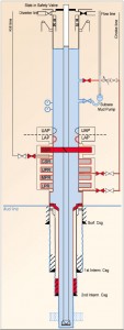
Often in conventional drilling, there is a series of common barrier elements in the primary and the secondary envelope. A failure of any of these shared elements will leave the well without any barrier. For LRRS Heavy, there are generally fewer common barrier elements. For example, the primary barrier is not dependent on the structural integrity of the last casing, the cement, the wellhead or the BOP body as long as the formation has sufficient strength with relation to the primary mud pressure and if the internal well pressure at seabed is lower than or equal to the seawater pressure.
In moderate water depths less than 4,500 ft, the LRRS may alleviate the shortcomings of conventional well control since it would not depend on the integrity of structural elements to maintain the primary barrier. This is because, with the LRRS, the mud pressure will not fracture the formation behind the last casing and there will be less pressure inside the riser at mudline than seawater pressure outside the riser. Hence, a structural failure of the casing, wellhead, BOP or riser will not constitute a well control event as the BHP would increase with the LRRS.
In deepwater, typically below 5,000 ft, the LRRS may be dependent on the same common barrier elements as in conventional drilling.
Primary barrier elements are:
• Drilling fluid;
• Riser pressure sensors (level control);
• Drilling riser;
• BOP body (common);
• HP wellhead (common);
• Casing (common);
• Casing seal assembly (common); and
• Cement behind casing (common).
Secondary barrier elements are:
• Casing and cement;
• Casing seal assembly;
• HP wellhead;
• Subsea BOP body;
• Subsea BOP element;
• Choke line and choke line valves; and
• Kill line and kill line valves.

Case examples
Two wells have been chosen to illustrate the potential use of the LRRS. Case 1 represents a typical GOM example, and Case 2 is based on publicly available Macondo data (Table 1). The casing program, pressure window and mud data for Case 2 are taken from the investigation reports and may not be the exact numbers encountered in the well. The two cases represent challenging wells but with different water and total drilling depths to show the relative effects on system applicability.
Drilling mud window
The drilling mud window defines the operational area for mud weights. If the pressure gradient in the open-hole section drops below the formation pore pressure gradient, there is a risk of inflow into the well. Conversely, if the pressure gradient in the open-hole section exceeds the formation strength, losses may occur.
For conventional drilling, the mud gradient will be a vertical line starting at flowline level at atmospheric pressure conditions. The seawater gradient will be lower than most drilling fluid densities. The combination of deepwater and the rapid increase in pore/fracture pressures below the mudline result in a conventional mud gradient not fitting well into the mud window.
Since the mud gradients normally are plotted in relation to the drill floor level (RKB), the LRRS mud gradient approaches zero at the mud/gas interface in the riser and approaches a straight vertical line in very deep well intervals. Hence, the LRRS gradient is now a curve, which shifts to the left of the conventional line. The two case examples will show how the LRRS shifts the mud gradient profile so that it has a better fit within the operational window.
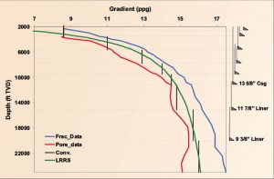
Drilling window – Case 1
Figure 3 shows the drilling window for Case 1. The planned conventional mud gradients are represented by black vertical lines (only the gradients in the open-hole sections are shown). The graph also shows that eight casing/liners and eight different mud weights were planned for the well. The conventional mud gradients almost cross the pore and fracture gradients, and the risk of taking an influx or a loss is significant.
The green line represents the LRRS mud gradient with only one mud weight. The LRRS gradient is close to zero (air gradient at atmospheric pressure) in the riser above the mud level. Since the gradient calculation assumes a completely filled riser, the LRRS gradient appears to increase with depth even though only one density is used.
In this well, the LRRS gradient fits into the drilling window from the first casing depth (surface casing) to total well depth. It would be possible to drill the entire well using a mud level in the riser of 1,600 ft below RKB and a mud weight of 17.2 ppg.
The LRRS gradient line does not approach the pore and fracture limits. This significantly reduces the risk with the LRRS of getting into an influx or loss situation compared with conventional drilling approach (represented by the vertical black lines).
With LRRS, the primary barrier in this well is always in place. Further, casing points can be selected based on criteria other than the gradient envelope. The well can be drilled with higher kick margins even if the casing program were reduced from seven casing strings below surface casing (conventional) to four casing strings. Use of LRRS would reduce both drilling time and cost and improve safety margins.
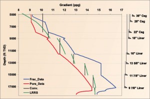
Drilling window – Case 2
Figure 4 shows the mud gradient window for Case 2. The mud gradients for conventional drilling are represented by vertical lines (black), and the green sloping lines represent the LRRS gradient.
The graph shows that LRRS mud gradients fit better within the operating window. As a result, the probability of loss by exceeding the fracture pressure is significantly reduced, allowing for safer and more efficient drilling. In the real operations of the well, there were substantial problems experienced with loss and gains through several hole sections, likely due to narrow pore and fracture pressure margins.
Kick margin Case 2
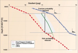
Kick margin is typically defined as the maximum volume of gas that can be circulated out of the well without fracturing the weakest formation in open hole. The actual pressure is an input parameter to kick-margin calculations.
Figure 5 zooms in on the 16-in. section for the Case 2 well, illustrating that LRRS will have reduced kick and fracture probability. The LRRS mud gradient is sloping and fits the deepwater drilling window better, which allows for greater margins toward both pore-pressure gradient and fracture-pressure gradient.
Riser margins
A riser margin is present if the mud weight used is sufficiently high to balance or exceeds the pore pressure if the drilling riser is disconnected from the BOP.
In nearly all conventional deepwater operations, the pressure at the disconnect point inside is higher than the external seawater pressure, resulting in no riser margin. If a riser margin is not present, a riser disconnect leaves the well with only the secondary barrier.
LRRS Heavy allows the use of heavier muds, making it possible to obtain a riser margin in many deepwater wells.
Riser margin Case 2
The Case 2 well was drilled conventionally without a riser margin. Using the LRRS, it is possible to achieve riser margins in all but the last section if the conventional casing program is used as a basis. Note that there was a pore pressure regression in the reservoir section (Figure 4). With a slightly modified casing program, setting the 9 5/8-in. casing below the high pressure peak at approximately 17,700 ft, a riser margin would be achievable.
Cementing
Getting a good cement job is a challenge, especially in narrow drilling windows. Conventionally, this challenge can be solved by reducing the circulation rate and using a low-density cement. Unfortunately, this can result in inadequate cement jobs and poor zonal isolation. Using the LRRS, it is possible to achieve improved cementing by compensating for density and ECD effects.
Cementing in narrow drilling windows
The limited pore/fracture window often limits the density of the cements that can be used and may lower the compressive strength of the hardened cement. This usually requires the use of lightweight lead cement (filler) and a smaller amount of conventional (tail) cement. The volume of tail cement may be just enough to cover the zone(s) of interest, plus some excess. Fluid losses, channeling or an underestimation of the excess volume required could leave the desired zone inadequately covered and without a barrier to prevent flow.
The lead cement, if left across a reservoir or pressured section, may not have enough compressive strength to provide a long-term pressure seal. The cement may not be strong enough to avoid cracking when the casing is pressured (and expands). In all cases, an effective barrier to the annular flow of fluids/pressure may not be present over the life of the well.
It should be noted that use of lightweight lead cement is a common and effective option and is not only used when a narrow pore/fracture gradient window is encountered.
The limited pore/fracture pressure may also limit circulation rates while pumping the flushes, spacers, cements and displacement fluids during the cement job. This reduces the overall displacement efficiency, potentially leaving pockets of gelled mud, mud filter cake and cuttings beds. This can result in a flow channel in the annulus.
If the cement has insufficient strength when the casing is pressured, a micro-annulus around the casing can be formed. This can happen even if the cement fully fills the annulus. Again, this reduces the cement’s effectiveness as a barrier.
Another issue to consider is timing for setting of the casing seal assembly or liner hanger seal in deepwater and deep wells. The hydrostatic head of the mud/liquid above the seal is lost. Only a small leak of fluids to the formation above the cement may initiate a cross-flow between formations, before the cement is cured.
Because this effect received little attention before Macondo, little work has been done to shed light on this effect. The LRRS may reduce the risk of gas migration during the cement-curing period. At any rate, operators should evaluate their procedures as to when the casing/liner seals are set after a cement job.
Cementing – Case 2
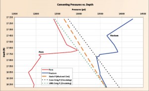
The example illustrated in Figure 6 shows a narrow pore/fracture window in an 8 ½-in. section during cementing operations. The orange line shows the annular pressure profile of 14.2 ppg mud to 17,160 ft and 16.7 ppg cement below to 18,300 ft.
With conventional circulation, the ECD effect shifts the hydrostatic pressure profile to the right (dotted black line) where it exceeds the fracture pressure, which can lead to formation fracturing, lost returns and, ultimately, an unacceptable cement job.
However, with LRRS (Light or Heavy), the fluid level in the riser can be dropped to compensate for the ECD effects (dotted green line) to reduce or eliminate the risk of fracturing the formation to obtain a better cement job and zonal isolation. If the only available circulation technique is conventional, one would be required to reduce the densities of various volumes of the cement/spacer slurries to compensate for the ECD effects.
Influx and loss detection
Influx and loss detection is improved in LRRS compared with conventional drilling. If an influx occurs during steady-state operations, more volume needs to be pumped out of the hole than what goes in. As a consequence, the pump speed and power will increase, which will be picked up by the control system linked to the level in the riser.
Note that the level in the riser is not affected by rig movement like the conventional mud line on a floater.
It may no longer be required to put the well on observation for flow checks or wait for a sufficiently large pit gain to accurately detect an influx. Pit gain would be the ultimate result, but with more accurate flow measurements, well control procedures may be initiated earlier.
When a potential influx is detected, the procedure is to immediately turn down or stop the LRRS return pump. This will increase the riser level and BHP.
Circulating out an influx with LRRS Heavy
With LRRS Light, the influx can be safely circulated out using conventional well control procedures, but LRRS Heavy requires special well control procedures. LRRS well control procedures are based on the driller’s method of circulating out with constant drill pipe pressure adjusting a subsea choke. Detailed procedures have been presented at the IADC Well Control Asia Pacific 2009 Conference and the 2010 IADC Well Control Europe Conference.
In the scope of this article, the principle differences between conventional circulation procedures and the LRRS Heavy procedures are explained:
1. Drilling with LRRS Heavy means that the mud weight is higher than the maximum achievable kill mud weight conventionally.
2. The well may not be shut in with the drill pipe full of drilling fluid as conventional. Either of the two alternatives below would prevent the formation from “seeing” the hydrostatic pressure of the drilling fluid from surface:
a. Install a drill pipe differential pressure valve.
b. Initialize the LRRS circulation procedures and U-tube the drill string prior to closing the well.
3. The choke line incorporates a subsea choke valve and a low-pressure bypass from the choke line into the main bore of the riser a distance above the outlet to the LRRS pump.
4. The well can be brought to overbalance dynamically by increasing the mud level in the riser; hence, there is typically no need to weight up the mud.
5. The BOP is normally closed during a kick circulation, but there may not be a hurry to shut in the well by closing a BOP element.
6. The kick is circulated out of the well using the constant drill pipe pressure (CDPP) principle, where CDPP is kept constant by regulating the pressure on the subsea choke valve. Alternatively, a minor influx can also be circulated without shutting in the well (closing a BOP element) and regulating the liquid height.
Influx simulation – Case 2b
This section describes how LRRS can react to an influx. The simulations are based on a transient two-phase flow model specifically adapted for the system. The flow simulator is a one-dimensional, drift-flux model, where a mixture impulse equation and a mixture energy equation are solved simultaneously with the pressure equation and a slip relation. Two separate mass balance equations are also solved with updated velocities.
In the simulations, any changes of LRRS or fill pump flow rates occur suddenly. The level controller is set to a constant level, and any flow of gas into the well is immediately compensated for by the LRRS subsea pump pumping out the same amount until inflow is detected and a control procedure has been initiated.
Dry gas and a compressible water-based mud of density 15.4 ppg at surface conditions were simulated. The mud level in the riser is initially 1,805 ft below the rig floor. The well consists of a 21-in. marine riser combined with BOP and a 9 7/8-in. casing. The casing shoe is at 17,168-ft TVD with a 8 ½-in. open hole below. The well is assumed vertical with a uniform 5-in. drill string. The flow rates from the rig pumps are 317 gal/min throughout the simulations.
The control system keeps the mud level in the riser constant until an influx or loss is detected. As soon as an influx is detected, the return pump is set to idle and the fill pump started, resulting in a mud-level increase in the riser. This is part of the LRRS well control procedures and will be followed by closing in the well at the subsea BOP (not simulated here).
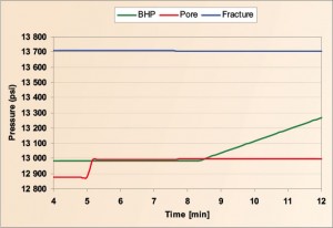
To illustrate kick detection, a simulated case with BHP below the pore pressure is used. Figure 7 shows pressure versus time. The green line represents the BHP. When the influx was detected three minutes after it started, the subsea pump was set to idle, causing the level and the BHP to increase.
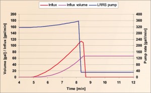
Figure 8 shows the influx flow rate, total gas volume in the well and LRRS subsea pump rate versus time. Since the subsea return pump was set to keep the riser mud level constant, pump speed has increased by 12% after 2 bbls of influx.
In this case, when the pump is slowed to idle, it will take less than one minute to stop the influx (only by increasing the level in the riser). The total gas volume in the well increases from zero to 67 gal during the four-minute duration of the kick. This equals a PI of 49 stb/d/psi based on 86-ft reservoir exposure.
It can be observed from the simulations that the subsea return pump will give a good indication of a kick. Further, when the kick is detected, the level can be increased to prevent further influx. This is an important benefit compared with a conventional drilling system where further inflow can be safely hindered only by closing in the well. For this specific case, there is still a large pressure adjustment available to the level in the marine riser to give a BHP that is safely above the pore pressure.
Conclusions
LRRS allows the mud gradient to better fit into the operating window in deep to medium-deep water and can reduce the risk of an influx or loss. The system can also improve kick detection and reduce kick size, as well as improve quality of primary cementing. As a result, this technology can improve safety in drilling of deepwater wells and infill drilling in depleted fields.
IADC/SPE 143095, “Well Control When Drilling with a Partly Evacuated Marine Drilling Riser,” was presented at the 2011 IADC/SPE Managed Pressure Drilling and Underbalanced Operations Conference, Denver, Colo., 5-6 April.
References:
1. BP incident investigation team, Deepwater_Horizon_Accident_Investigation_Report.pdf, BP, 8 September 2010.
2. Emilsen et al (Add Wellflow), Report-Dynamic Simulations Deepwater Horizon Incident BP, Appendix W of Deepwater_ Horizon_Accident_Investigation_Report.pdf, BP, 29 August 2010.
3. Halliburton, HAL-Production.Casing.Design.Report.4.15.2010.moderate.pdf, BP, 15 April 2010.
4. Børre Fossli, Ocean Riser Systems, Sigbjørn Sangesland, NTNU; Drilling and Well Control Procedures using a partially evacuated Marine Drilling Riser; IADC Well Control Europe, Aberdeen 13-14 April 2010.
5. Børre Fossli et al, Well Control Procedures in Subsea Drilling Using a Partly Evacuated Marine Drilling Riser, IADC Well Control Asia Pacific, November 2009, Thailand.




Could I please be put in touch with the authors of this paper as I would like to organise a meeting to discuss the technology.
Thank you,
Mike Vander Staak
Hess Corporation
*1 713 496 4110