Indonesian 2-well UBD campaign cuts reservoir damage and more in marginal heavy-oil field
By Tomoyuki Kitamura, Hasan Zaki and Kitos Akbar, Kangean Energy Indonesia; Felbert B Palao, Julius Ceazar L Sosa, Julmar Shaun S Toralde, Steve Nas, Weatherford
The oil from the Ngimbang Carbonate reservoir in Sepanjang Island, East Java, Indonesia, is composed mostly of heavy black oil with a pour point of 120°F and a wax content of 24.89%. Its specific and API gravity are 0.8574 and 33, respectively, and the bottomhole temperature is 223 °F.
Underbalanced drilling (UBD) operations in this high-pour point oil marginal reservoir, for two wells, SED-3 and SED-4, were planned to achieve the main goals of improving reservoir productivity, avoiding reservoir damage, enabling fracture identification and making testing while drilling possible. Secondary benefits expected by employing UBD included avoiding drilling fluid losses, increasing the rate of penetration and minimizing drilling problems.
This article presents the details as to how the challenges of drilling in UBD mode in a reservoir with high-pour point and waxy oil were addressed in the planning stage and how the UBD program was implemented.
The circulating system for the UBD operation was designed with the ability to heat the fluid system to above the pour point to avoid solidification of the fluid. The drilling fluid was to be heated to 160°F and kept at this temperature to prevent damage to the drilling elastomers. Agitators were installed on all tanks to prevent wax formation.
INTRODUCTION
Sepanjang is a marginal oilfield that is part of the Kangean PSC block operated by Kangean Energy Indonesia (KEI).
The primary geological objective of drilling operations in Sepanjang is the Ngimbang Carbonate Formation, which is a tight carbonate reservoir located at a depth of approximately 4,500 ft to 4,700 ft VD. The reservoir pressure is around 2,150 psi at a depth of approximately 4,400 ft VD, which corresponds to a maximum pressure gradient of 9.39 ppg.
Historically, three wells have been drilled into the Ngimbang reservoir. The first was exploration well SED-1, was drilled by Arco in 1990. It confirmed the presence of crude oil with high wax content. In 2006, SED-2 and SED-1A were drilled.
To further enhance production from the small accumulation of oil in the fractured reservoir of Sepanjang, two more development wells, SED-3 and SED-4, were drilled in 2008. The main objective was to test the reservoir further southeast of the Ngimbang Carbonate structure.
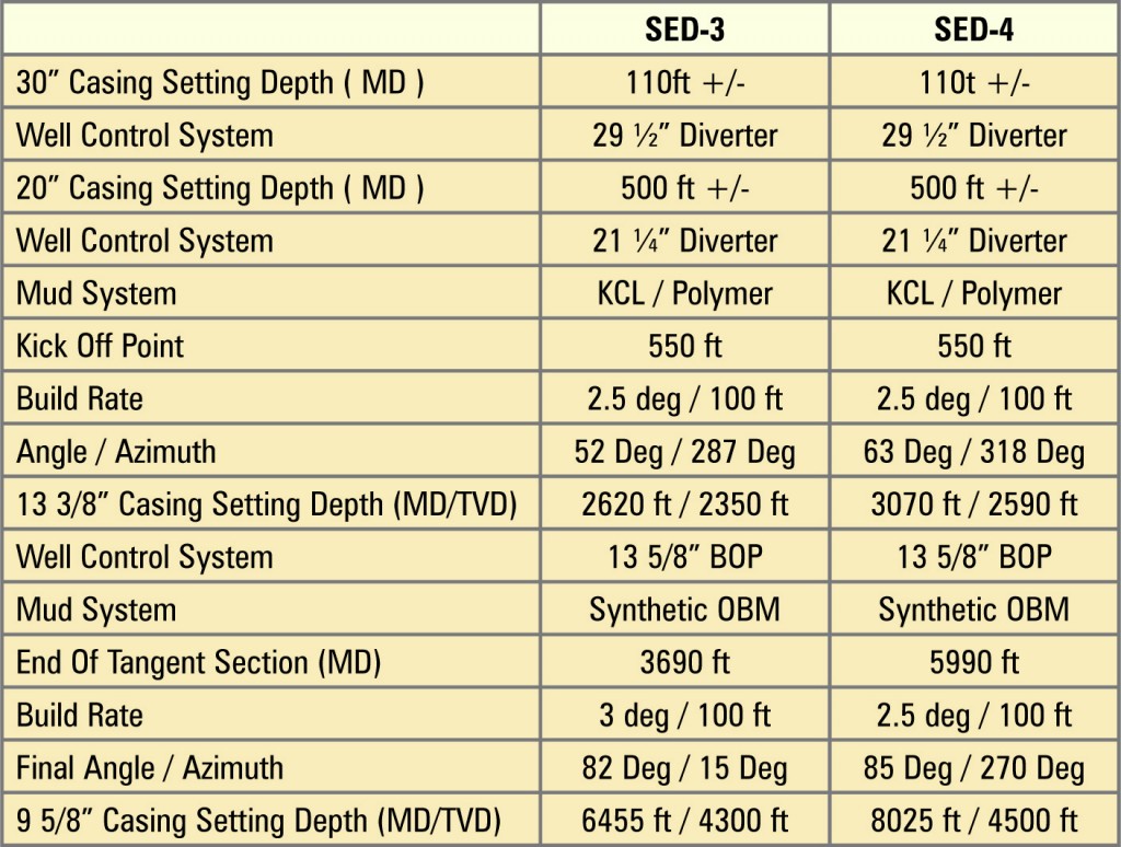
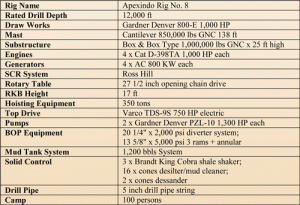
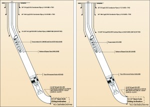
UBD was used to enable production testing while drilling to identify production zones, as well as to reduce reservoir damage. This article focuses on these two new development wells, drilled with Apexindo Rig No. 8. The well schematics for SED-3 and SED-4 are provided in Figures 1 and 2. Drilling operation summaries for the two wells are presented in Table 1.
PLANNING, PREPARATION
UBD suitability evaluation
To assess the suitability of UBD in drilling the reservoir section of Sepanjang, reservoir data was analyzed using UBD suitability software. The UBD suitability score distribution, which showed a mean score of 45, indicated that the Ngimbang Carbonate is an average to good UBD horizontal well candidate. Based on the current reservoir description, UBD can increase reservoir productivity by minimizing potential damage and by intersecting conductive natural fractures.
Circulation system
The high-pour point oil produced in Sepanjang meant that the active system during UBD operations must be able to heat the produced crude oil and the drilling fluid above the pour point of the crude to avoid solidification of the produced fluid.
Diesel was planned as the drilling fluid for the UBD section. With the pressure gradient of the reservoir at 9.39 ppg, using diesel would render the system sufficiently underbalanced without the need for additional gas injection. Using an oil-based fluid system would also help to reduce any potential reservoir damage.
As drilling progresses, produced crude oil was to be mixed with the diesel as part of the active system. Any excess crude was to be exported to the FSO (floating storage and offloading) facility using the production pipeline.
The diesel and crude oil in the active system was designed to be kept at 160°F for optimal solids segregation and to avoid damaging the elastomers in the rig pump and the kelly hose. The export tank where excess crude will be stored was to be kept at 190°F, ready for export to the FSO facility.
To ensure that well control can be maintained in emergency situations, a kill fluid volume double the hole volume was to be maintained at surface. The kill fluid is a weighted oil-based mud that should not contain any reservoir crude. The IADC UBO/MPD code for these wells is 2-B-5. This is derived from the fact that the reservoir pressure in Sepanjang is only 2,150 psi, meaning the well will flow, but conventional well control procedures still apply, which translates into a Level 2 well classification. Also, the wells will be drilled underbalanced (B) using a single-phase drilling fluid (5).
Bottomhole pressure
The 8 ½-in. section of the wells was to be drilled underbalanced at a target drawdown of 50 psi, which is set to avoid water production due to water coning. The reservoir was expected to flow while drilling underbalanced at the planned 50-psi drawdown. Overbalance during drilling was to be avoided to minimize skin damage as much as possible. The wells could also be drilled at balance or at a smaller drawdown to reduce reservoir inflow, if required.
With the drilling fluid density set at 7.1 ppg in order to maintain a 50-psi drawdown, surface choke pressure would need to be applied. Pumping at a flow rate between 350 gpm and 500 gpm, an annulus friction of between 50 psi and 100 psi needed to be factored in as the bottomhole pressure needed to be controlled.
Flow modeling
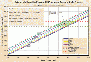
Figure 3 shows the flow model for UBD operations in Sepanjang. It graphs the bottomhole pressure against different pump rates and choke pressures. The shaded area indicates the operating envelope, where the various constraints during UBD operations are fulfilled. These constraints are minimum annular velocity, min/max motor equivalent liquid volume and the target drawdown.
For proper hole cleaning, the acceptable minimum liquid velocity through the entire annulus was set at 150 ft/min. It also factors in the fact that a 6 ¾-in. drilling motor with a liquid flow rate range of 300-600 gpm was to be used.
Equipment setup, process flow
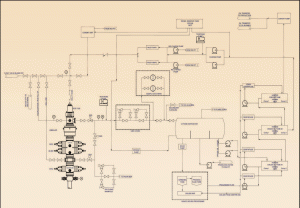
The main UBD equipment used in the wells’ UBD operations were:
• One unit high-pressure rotating control device.
• One unit choke manifold, sampler and pump house skid.
• One unit horizontal four-phase separator.
• One unit 50-ft flare stack.
• Four units 400-bbl enclosed storage tank with heating coil.
• Two units 400-bbl enclosed storage tank (no heating coil).
• One unit double pump skid for sparging with two 10 HP centrifugal pump.
• One unit centrifugal pump 10 HP.
• Two units centrifugal pump 25 HP.
• One unit centrifugal pump 75 HP.
The tank farm system consisted of six 400-bbl storage tanks that were used to heat the injection and produced fluid. One tank was used solely for storing and heating clean diesel, which was used for flushing any part of the circulating system that was exposed to the crude and becomes static. Three tanks were used to store and process fluid returns for solids removal and was referred to as the “active tanks.” Two tanks, referred to as “storage tanks,” stored and heated excess crude production that was later reinjected into an adjacent well.
The absence of production facilities in the area constrained the storage capabilities for produced crude during drilling operations, leaving no option but to have crude reinjected into an adjacent well (SED-3), which was also drilled in UBD mode. This practice is not recommended for wells drilled in underbalanced mode, as it offsets the benefits of UBD.
In this case, a hole-cleaning program by coiled-tubing acidizing was conducted later on SED-3, and this restored its production capabilities to the same level as when crude had not been reinjected.
Four tanks were lined with steam coils and heated by a steam generator. Fluid is constantly circulated between the tanks to heat the other two tanks with no steam coils installed. A jet line sparging system, which used two 10 HP centrifugal pumps, was installed on active and storage tanks to prevent wax settling and to circulate fluid between tanks. A 10 HP centrifugal pump was also installed to enable pumping from the active tank to the storage tank or vice versa.
Two CD-500 centrifuges were installed on top of two active tanks to remove solids from the active tanks during the drilling operation, and one CD-600 centrifuge was rigged up with the two storage tanks for further solids removal before the drilling fluid is pumped down the hole.
The two rig pumps were used for fluid injection. One 75 HP centrifugal pump (pre-charge pump) was used to feed the rig pump through a 4-in. pre-charge line. The pre-charge pump was lined up to take supply from either of the six 400-bbl tanks. A 25 HP centrifugal pump was also installed on the pre-charge line, serving as backup to the 75 HP pump, as well as a flush pump for the suction lines for extended hours with no circulation downhole.
Annular returns were diverted from the RCD into the 4-in. 6,000-psi primary flow line, where it was flowed into the 4-in. UBD choke manifold, into the sample catchers and into the four-phase separator. A secondary 4-in. flow line was installed from the rig choke to the separator, and another 4-in. hose was installed from the rig choke to the shale shakers.
From the separator, the solids slurry was shipped via a 2-in. line using a screw pump to the solids-processing system. The cuttings were processed in the grinding tank and were stored in a solids skip, while recovered drilling fluid was sent from the solids-processing system to the active tanks.
As no water production was expected, both the water leg and the oil leg of the separator was lined up for pumping into the active tanks on two separate 4-in. lines. A 20 HP centrifugal pump was also added on the water leg line to allow the separator pumps to keep up with the transfer rate to the active tanks with the rig pump injection rate and reservoir production rate.
Both 4-in. lines were installed with a bypass line to the waste pit in case there was any water production. The gas and the PSV line from the separator was sent to the flare via two separate 4-in. lines. Nitrogen bottles were connected to the separator to maintain positive vessel pressure during the underbalanced drilling operation. The cement pump was connected to the two storage tanks, and the diesel tank and was used to bullhead the drilling fluid down the well through the kill line.
Two conventional non-ported float valves were run immediately above the bit and above the MWD tool in the BHA. In addition, one NRV was run in the string prior to the bit exiting the 9 5/8-in. casing, with additional NRVs placed in the string at increments of 500 ft of hole drilled.

Floating mud cap
Under normal circumstances, the well will not be killed due to concerns with lost circulation and damage to the reservoir. Flowing the well while tripping out with the BHP maintained within the target drawdown of 50 psi will mean that the wellhead pressure (WHP) while tripping will be around 550 psi. With this WHP, a “pipe light” condition exists at around 900 ft, which would require a snubbing unit.
To eliminate the need for the snubbing unit, it was planned that the wells will be balanced using a floating mud cap before any “pipe light” depth is reached. Using this method, overbalance and damage to the reservoir would still be avoided.
In this method, during trip out, the well will be flowed until the bit is inside the last casing shoe. A weighted oil-based mud will then be pumped on the annulus by bullheading through the kill line, with enough mud volume to balance the well, and the WHP will drop to 0 psi.
Tripping can then be continued to surface with no pressure on the wellhead.
IMPLEMENTATION, RESULTS
SED-3 UBD operations
Prior to drilling the 8 ½-in. section, oil-based mud in the well was fully displaced with diesel. The UBD system was then lined up, and hot diesel was circulated down the well through the drill pipe. The initial pump rate was 200 gpm, which was gradually increased to 425 gpm, as required for the MWD tool to transmit a mud pulse.
Gradually increasing the pump rate while circulating was done to observe if the UB system can keep up with a pump rate higher than what was originally written in the drilling program and allowed visual inspection of leaks in the rig-up.
After the UB system was observed to be functional, cement and the entire shoe track were drilled out, and drilling of the 8 ½-in. hole continued while maintaining a 50-psi drawdown.
Drilling of the new formation continued until the presence of shale was observed at 6,428-ft MD and confirmed at 6,493-ft MD. A sidetrack hole was drilled from 5,725 ft down to 6,440-ft MD, where a well test was conducted. The choke was closed for 1.5 hrs to allow pressure to build up in the well, increasing to 290 psi.
The choke was then gradually opened to its fully open position, allowing the well to flow. During the flow test, which lasted 2.5 hrs, there was a 35-bbl gain with a final flow rate of 1 bbl/15 min with a choke pressure of 1.5 psi.
Drilling then continued with the drawdown increased to ± 150 psi until TD for the well was reached at 7,580 ft. Another well test was conducted at TD. The well was shut in for an hour, allowing pressure to increase to 327 psi, and the choke was opened fully. A 592-bbl gain was seen at surface during the 4.75-hr testing period. No significant gas production was seen at surface, confirming the initial assessment that the reservoir has a very low GOR.
After the well test, crude was bullheaded down the well using the cement pump. After tripping out to 2,861 ft and displacing the upper section of the well with oil-based mud to create a floating mud cap, tripping out of the hole continued with 0 psi WHP.
A temporary completion assembly was run to 2,895 ft, which was to be used to inject crude that will be produced when drilling the second well, SED-4.
The rig was then skidded to SED-4, the BOP stack nippled down and the temporary Christmas tree installed. After drilling and completing SED-4, the rig was skidded back to SED-3, and well completion activities immediately followed.
SED-4 UBD operations
After the rig was skidded to SED-4, cement, shoe and new formation for the 8 ½-in. hole was drilled up to 5,590 ft using water, after which an FIT was conducted to 11.8 ppg. The well was then displaced with underbalanced drilling fluid, which was the crude/diesel mix used in SED-3.
Due to the uncertainty with regards to the actual reservoir pressure, it was decided to start drilling the 8 ½-in. underbalanced section at a bottomhole constant pressure (BHCP) of 1,900-1,935 psi, which gives a drawdown of about 200 psi.
UBD commenced from 5,590 ft and continued until 7,170 ft, when KEI decided to conduct a well test. Initial influx was seen at 5,900 ft, and a significant increase in production rate was seen at 6,600 ft, then fully open flow at 7,170 ft.
After the flow test, it was decided to conduct a lateral sidetrack, and drilling of the lateral hole commenced from 5,990 ft. Production was steady until a big influx was seen at 7,032 ft. From 7,032 ft to TD at 7,400 ft, the BHCP was maintained at 2,130-2,140 psi to minimize influx. Drilling was stopped at 7,160 ft to perform another flow test, and the well flowed at an average 600-psi WHP.
Full open flow was not conducted due to insufficient tank holding capacity. It was then decided to continue drilling until shale was seen to confirm the shale boundary. TD was called at 7,400 ft when shale was confirmed. During drilling, all the excess crude produced was injected down SED-3 using the cement pump.
Tripping out to 5,514 ft and bullheading of the upper section of the well with oil-based mud to create a floating mud cap was done, and tripping out of the hole continued with 0 psi WHP.
The completion packer was set at 4,640 ft, and after the completion tubing and Reda pump was run, the BOP and RCD was nippled down. The rig was then skidded to SED-3, and after the Christmas tree was installed, the completion annulus was displaced to a diesel/crude mix, and the completion tubing was displaced to diesel.
CONCLUSION
UBD was used in the Sepanjang Field to drill the 8 ½-in. holes in wells SED-3 and SED-4 in order to achieve the goals of improving reservoir productivity, avoiding reservoir damage, enabling fracture identification and enabling testing while drilling. Secondary benefits include avoiding drilling fluid losses, increasing the rate of penetration and minimizing drilling problems.
In SED-3, the goals of improving reservoir productivity by minimizing, if not totally avoiding, reservoir damage was achieved. Fracture and formation identification was also made possible, enabling the decision of cement plugging the original hole when shale was encountered to be made at the right time.
The goal of enabling testing while drilling was also achieved by allowing a flow test at 6,440 ft. After the first flow test, drilling of new formation continued until TD was reached at 7,580 ft. Another flow test was conducted at TD, confirming that the desired production rate was already achieved, and drilling ahead or drilling a new lateral is no longer required.
The secondary goals of minimizing fluid losses and minimizing drilling problems were also achieved. The goal of increasing the penetration rate cannot be directly proven, but the section was drilled with an average 35 ft/hr ROP without sacrificing hole cleaning.
For SED-4, the objective of production testing while drilling was achieved, as it enabled the operator to correctly decide to stop drilling the original hole and to drill a lateral hole. Drilling the lateral hole was not in the original plan, but data collected during the flow test of the original hole supported the fact that production from the original hole was insufficient; thus the decision was made to drill a lateral hole.
The original hole was drilled underbalanced from 5,580 ft to 7,170 ft, while the lateral hole was drilled underbalanced from 5,990-ft to 7,400-ft TD. The original hole was open and producing during the drilling of the lateral hole. No hole problems were encountered during the drilling of both holes.
The goal of reducing the reservoir damage was also achieved as the 8 ½-in. section was drilled underbalanced throughout the section. The use of the floating mud cap during trip-out was successful, and this avoided the need for a snubbing unit. This technique could be used on future UBD wells where the GOR is small and there is no danger of gas migration.
When the steam boiler went down, there was danger that the UB fluid in the tanks would solidify once the temperature went down sufficiently. This was rectified by adding diesel into the active system to lower the pour point of the UB fluid. It was fortunate that the boiler was repaired after 5 hrs, or it would have required a lot of diesel to dilute the system. It is recommended that a pour-point depressant chemical be available on location to assist if such a problem occurs.
Based on the well objectives achieved and the oil production levels witnessed in the Sepanjang Field, it would be fair to conclude that employing underbalanced drilling in the development of this marginal heavy-oil reservoir is greatly beneficial.
References
Bourgeois, Gilles David, Joanne Chu, Jan Hendrik Terwogt, Awang Kasumajaya Mahran and Alberthnego Wisnugroho: “Under-Balanced Drilling Experience in a Shallow Clastic Oil Field, Offshore Sabah, South China Sea”. SPE Paper 80455 presented at the SPE Asia Pacific Oil and Gas Conference and Exhibition held in Jakarta, Indonesia, 9-11 September 2003.
Park, D., P.R. Brand, B. Allyson and G. Sodersano: “Planning and Implementation of the Repsol-YPF-MAXUS Krisna Underbalanced Drilling Project”. SPE Paper 67689 presented at the SPE/IADC Drilling Conference held in Amsterdam, Netherlands, 27 February-1 March 2001.
Pickles, Rob, Pat Brand and Pat Savage: “Utilization of Underbalanced Drilling Techniques to Exploit a Low-Pressure Reservoir in Indonesia”. SPE Paper 91591 presented at the SPE/IADC Underbalanced Technology Conference and Exhibition held in Houston, Texas, 11-12 October 2004.
Rehm, B. 2002. Practical Underbalanced Drilling and Workover: Petroleum Extension Service, University of Texas at Austin, Continuing and Extended Education, Austin, Texas; United States of America.
This article is based on SPE/IADC 130314, presented at the SPE/IADC Managed Pressure Drilling and Underbalanced Operations Conference & Exhibition, 24-25 February 2010, Kuala Lumpur, Malaysia.

