Highly instrumented toolstring platform delivers greater control, power distribution in completion manipulations

By Stephen Whitfield, Associate Editor
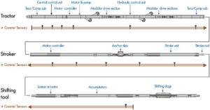
Electric line-powered toolstrings – consisting of a wireline tractor, stroker and a shifting tool – are commonly used to manipulate downhole completion components like formation isolation valves, inflow control valves and sliding sleeves. However, as operators drill more complex wells with smaller inner diameters, these toolstrings have become more difficult to deploy.
“We need more complex devices to navigate through these restrictions,” said Payam Tabrizi, Engineering Project Manager and Systems Architect at Altus Intervention. “We need devices with features like high expansion anchoring and improved shifting capabilities, and we need devices that can deliver the force needed to effectively manipulate these downhole devices.”
Last year, Altus deployed a new electrohydraulic manipulation toolstring with added sensor instrumentation with the high expansion anchoring and shifting capabilities needed to work in wells with smaller ID restrictions. The toolstring’s optimized electric and hydraulic power distribution, combined with the increased level of instrumentation compared with previous tractor/stroker tool platforms, enables greater control of completion manipulation operations. This increased connectivity can help enable greater real-time visibility of and engagement with the downhole components. Mr Tabrizi discussed the development and deployment of the toolstring at 2022 SPE/ICoTA Well Intervention Conference on 22 March.

Toolstring platform design
Unlike with previous toolstring platforms, Altus designed each tool within this new platform on a common architecture. This connects their instrumented nodes and sensors on a central control unit that receives all sensor measurements and handles and routes all commands provided by personnel at the surface. Additional sensors measuring tension and compression were added above and below the tractor, and additional sensors measuring the pull force on the electric line cable, push force on the tool string and the stroker anchor force. Mr Tabrizi said the added sensors enable greater electric power control than a conventional platform, as users now have a better understanding of power distribution between different components within the toolstring.
“One advantage of this approach versus traditional systems, where you only have power supplied at the surface, is that it allows it to optimize your tool for the sequence of events that are happening in the well,” Mr Tabrizi said. “With a traditional system, you couldn’t control where the power was going. Your tractor speed was constant from the surface all the way to total depth. But here, we can decide to deliver all of the power to the tractor and go fast to a desired depth, and then reduce the power once we reach that depth because we don’t need to go as fast anymore.”
The stroker tool maintains some features from previous models. In particular, it has a self-locking actuator to prevent stroke creep once stopped at the prerequisite stroke position. As a safety precaution, stroke force and sweep limits can be set, and re-set, if a cautionary approach to shifting is deemed necessary.
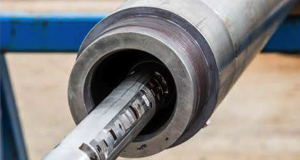
Although it was built with a 2.5-in outer diameter and is slick when inactive, the stroker has been designed with high expansion tri-anchor slips. These slips allow the stroker to be set in tubulars with an ID of up to 6.6 in. and provide a controlled stroke pull/push force of up to 30,000 lb/ft. Mr Tabrizi said that level of force is far greater than the amount of force typically needed for shifting or shearing downhole completion components. However, it allows for considerable additional force to be applied when needed – for instance, when accumulated scale debris hinders a sleeve from shifting.
The accompanying instrumented shifting tool is also slick when inactive, with high expansion positioning of three radially spaced shifting dogs up to an inner diameter of 5.3 in. To handle this level of expansion, the shifting dogs are incorporated in a hydraulically driven centralizer, which is expanded to bring the dogs into close proximity of the completion component profile in which they are to engage.
Relevant tool parameters are displayed in real time on a dashboard throughout the entire sequence of engaging the shifting tool with a targeted completion component profile. The dashboard also shows stroke force and stroke sweep from a given operation and allows users to compare these figures to those captured during engineering trials or pre-job surface integration tests.
The shifting tool was also designed to incorporate a lead impression block, which enables a lead impression tell-tale to gather physical information during an operation if desired. Mr Tabrizi said this functionality can be useful in cases where suspected debris has caused sleeve engagement challenges, or when a valve is suspected to be closed.
Testing and operations
Engineering tests were carried out during tool development, using shifting dogs designed specifically to mate with targeted sleeve profile of various completion components. Replica sleeves with example profiles were manufactured, and shift tests were conducted to test the dog engagement in the sleeve for shift down and shift up sequences, force measurement accuracy, manipulation repeatability and string rigidity.
The tool has also been tested and mobilized for a contingency formation barrier isolation valve manipulation operation in Asia and utilized on multistage completions in the North Sea. At the conference, Mr Tabrizi presented a case study from a North Sea operation where an unnamed operator needed to close six multistage frac sleeves that had been deployed as part of a well’s lower completion string.
The sleeves were positioned in the horizontal section of the well at a measured depth of around 16,000 ft. An earlier attempt to close the sleeves had been carried out using an off-the-shelf shifting tool and a standard, non-instrumented linear stroker device. During that operation, the shifting tool repeatedly slipped out of the sleeve profile, preventing the operator from applying the stroke force needed to shift the sleeve. The operator suspected that scale build up had potentially led to some seizing of the valve sleeve, further complicating the operation.
The operator chose to use the new stroker and extended-reach shifting tool for the operation. The tool string had a small and slick outer diameter when deactivated to enable its passage through the completion. Once conveyed to task depth, the shifting tool’s proximity centralizer was expanded. The tool was pulled up by a winch to a position and engaged the shifting dogs in the sleeve’s profile. The stroker was then anchored in the completion.
Altus conducted extensive interference testing between this manipulation toolstring and the frac sleeve at its engineering facility. The test replicated the sleeve shifting sequence required for the specific field operation to verify its effectiveness. With the stroke force capability far exceeding the factory specifications from the sleeve manufacturer, there was additional force available to overcome any potential sleeve seizing. Also, the toolstring’s instrumentation, coupled with its real-time control and limit triggers, enabled greater visibility and verification of the shifting of each sleeve before moving to the next, and before pulling out of hole.
The operation in the North Sea field was carried out successfully, with all six sleeves being shifted in a single run. Some of the sleeves required force much higher than the 300-kg requirement specified by the OEM to be shifted – Mr Tabrizi said one sleeve needed as much as 5,000 kg of force.
These higher forces, coupled with real-time pressure readings from the shifting tool’s proximity centralizer and tension data from the tractor’s lower tension/compression sub, combined to provide a higher level of certainty throughout the sleeve shifting sequence. This allowed the engineer to better understand the in-situ situation and take immediate and controlled corrective action, circumventing a false shift scenario due to sleeve seizing and the shifting tool slipping out of the shifting profile, enabling the operator to successfully shift each sleeve without issue.


