Accurate wellbore trajectory delivers 70% more reservoir contact with Gullfaks sidetrack well
By Linn Arnesen and Anna Karina Aune,StatoilHydro; Graham Raeper, Schlumberger
The Gullfaks field is located in the central part of the East Shetland Basin in the Northern North Sea and was discovered in 1979. The StatoilHydro-operated field has been developed with three Condeep gravity-based concrete structures and started production in December 1986. The field was the first major development by an all-Norwegian consortium. Peak production of over 600,000 bbl/day of oil was achieved in 1994, with the recovery factor currently approaching 60%.
 Figure 1: The B-12 AT3 well plan indicates the difficulties encountered after a relatively uneventful drilling of the 12 ¼-in. build section.
More than 200 wellbores have been drilled in the field to date. It is estimated that out of a total recoverable oil of 2.265 billion barrels, some 126.4 million barrels remain, with current production averaging 91,000 bbl/day (figures from 31 December 2008), although the aim is to further improve the recovery factor in the field.
To achieve the highest recovery from the field, drilling continues today, targeting unexploited zones identified from advanced reservoir modeling and 4D seismic processing. As all drilling slots have been used, drilling consists mainly of re-entry work, typically sidetracking from windows milled in the casing and drilling laterals to tap unexploited zones. Geometric steering is mainly used, and many wellbores attempt to penetrate multiple zones, not only as production targets but also to obtain information to enhance the reservoir model.
Drilling is very challenging due to several factors:
• Possibility of encountering depleted zones or virgin zones in the same borehole.
• Considerable faulting.
• Sedimentary structures weakened by years of production.
• Potential for severe drilling fluid loss.
• Reservoir model uncertainties due to the complex structure.
On the majority of wells, StatoilHydro drilling parameters are adjusted to follow the LEDO (low energy drilling operations) principles presented by Blaasmo, et al.
Primarily, with these procedures, changes in drilling parameters are implemented one at a time so the results can be evaluated before further changes are made.
This methodical approach is designed to facilitate root-cause analysis if any unexpected events occur. Additionally, strict adherence to the operational mud weight window is essential, through careful monitoring and control of the ECD, including reduction of ROP if required to ensure good hole-cleaning and reduce cuttings load.
On wells where the operational mud weight window (defined as being between the minimum fracture and maximum pore pressure) is particularly restricted or absent, a managed pressure drilling (MPD) technique is employed, using a rotating control device to control overbalance, enabling the use of as light mud weights as possible while not inducing reservoir formations to flow.
In the well that is the subject of this article, the B-12 AT3 well, there were two drilling objectives: the Tarbert D4B and D5 reservoir segments. The D4B was believed to be the reservoir formation, and the D5 was an unexplored block with a low probability of producible hydrocarbon.
A CHALLENGING PLAN
The plan was to mill out of the 13 3/8-in. casing in the motherbore, then drill a long 12 ¼-in. step-out and land the wellbore in the Tarbert. Once in the target formation, the objective was to drill at least 1,000 ft (300 m) in the D4B block, then penetrate the D5 block (Figure 1). The well trajectory was intended to stay as close to the reservoir top as possible – within 7 ft (2 m) – to maximize access to attic oil while avoiding drilling up into the sometimes unstable Shetland shale overburden.
This plan would also minimize the chance of drilling into the oil/water contact (OWC) lying below the planned well path. Under ordinary circumstances, the well could be landed and the lateral section drilled using geometric steering. However, experience in the area had shown that drilling may be extremely challenging.
Unexpected fluid losses while drilling were a constant possibility, demanding frequent use of lost-circulation material to minimize mud losses.
 Figure 2: PeriScope inversion through the D4B reservoir section of the Tarbert formation illustrates the drilling challenges. The well plan (solid green) line is contrasted with the as-drilled line (solid red). The BCU is shown as a dashed green line above the well track. A dotted green line and solid blue line show the base of a silty layer of poorer quality reservoir and the OWC respectively. Red boxes indicate steering decisions.
The 12 ¼-in. section was drilled without incident. However, from that point, things proved not so simple. After drilling only 650 ft (200 m) out of the 9 5/8-in. casing shoe with an 8 ½-in. bit, severe fluid losses were encountered. None of the usual cures were successful, and the well had to be sidetracked. The same problem occurred twice more within a few hundred feet, requiring the drilling of two more sidetracks. Finally, a protective casing was set and the decision was made to run a 7-in. liner and drill out with a 6-in. bit. Geomechanical modeling and log analysis indicated that the losses were associated with the proximity of major faults in the reservoir and the juxtaposition of the depleted Tarbert reservoir and a downthrown block of the Shetland group. The problems encountered in only a short interval had set the project schedule back around 40 days behind the target time.
EYES ON THE PROBLEM
Having experienced so many problems just getting to the target reservoir, the risk of drilling out of zone into the unstable Shetland shale overburden became unacceptable – the potential of further fluid losses and major drilling delays was clear.
Additionally, information obtained from the geology encountered so far increased the uncertainty of the reservoir structural model. The decision was made to shift the geometric target for the well trajectory down about 52 ft (16 m), although even this did not guarantee that the well would not penetrate the potentially troublesome Shetland shale. This also meant that significant attic oil could have been bypassed.
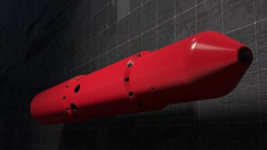
Because of the risks involved, geometric steering was ruled out, and StatoilHydro elected to geosteer using real-time information from the Schlumberger PeriScope boundary-mapping tool. This logging-while-drilling (LWD) tool provides a very deep-reading, azimuthal electromagnetic propagation resistivity measurement. With its ability to detect bed boundaries and other drilling hazards as much as 21 ft (6.4 m) radially from the tool in any direction, the tool appeared to offer the best chance to meet the drilling objectives. Most importantly, early warning of approaching hazards allows sufficient time to make a toolface adjustment to avoid the hazard altogether, thus eliminating the need to pull back and sidetrack, a risky and time-consuming solution. This factor alone justified the added cost of the geosteering well-placement tools and services, and their cost was determined to be far less than the potential rig time drilling sidetracks estimated from prior experience.
Prior to drilling, members of the Gullfaks drilling team and Schlumberger well placement experts met to model and plan the geosteering operation. Deepening the well profile was expected to allow the lateral section to get off to a good start within the heart of the Tarbert; then the geosteering tool could make the fine adjustments necessary to maintain minimum distance from the reservoir top. A real-time operations support center was set up. A collaborative web viewer was used so each member of the team could have 24/7 access to drilling progress, including real-time visualization of the wellbore profile and direction with respect to the formation boundaries.
The objective was to drill at least 1,000 ft (300 m) in the Tarbert D4B oil zone. The boundary-mapping tool and other LWD tool response could ensure that the wellbore tracked with high-quality reservoir “sweet spots” encountered along the way. Besides the boundary-mapping measurement, the bottomhole assembly included arcVISION array resistivity measurements, near-bit azimuthal gamma ray and the adnVISION azimuthal lithodensity/neutron tool. The all logging tools were 4 ¾-in. diameter.
As drilling progressed, observers were presented with a mosaic of quantifiable data and images. By inverting the data in real time, a sectional profile of the wellbore trajectory emerged that clearly indicated the well track with respect to the formation top. The Base Cretaceous Unconformity (BCU) was to be avoided as it marked the line of demarcation of the Shetland shale. It was possible to geosteer the bit to maintain the well’s trajectory within 2 m of the BCU. Profile shadings indicated the highest-quality reservoir sections and polar plots could be taken at any time to indicate the proximity and dip of both the overlying and underlying bed boundaries. The wellbore successfully traversed the D4B block and entered the water-saturated D5 block. As the bit approached the OWC, the boundary-mapping tool detected it and profiled it clearly (Figure 2).
RESULTS EXCEEDED EXPECTATIONS
The B-12 AT3 well was successfully geosteered for 1,748 ft (533 m) in the Tarbert D4B sweet spot. The troublesome overlying shale was not penetrated, and no sidetracks were required as the well trajectory was placed entirely within the reservoir. The well achieved in excess of 70% more sand exposure than expected. The entire reservoir section was drilled with a single bit run. Excellent hole quality and good wellbore cleaning enabled the production liner and completion strings to be run to successfully tap the Tarbert D4B block.
Most importantly, the well was tested and flowed 10,648 bbl/day (1,700 standard cu m/day) – a 250% increase over the reservoir’s mid-case estimated production. The well is producing at 6,285 bbl/day (1,000 standard cu m/day) with no water cut.
From the point of view of the combined drilling team, the availability of definitive information and the clarity of the real-time presentations enabled informed decisions to be made with confidence. A total of 14 steering decisions were made along the course of drilling the lateral. Where delicate steering is needed for accurate well placement and hazard avoidance, high technology solutions can be valuable. Well productivity can be maximized and the added cost offset by reduced sidetracking and time spent curing drilling and circulation problems.
This article is based on a presentation at the IADC World Drilling 2009 Conference & Exhibition, 17-18 June, Dublin.
Reference: Blaasmo M, et al, 2007, “Detailed Post-Event Analysis of Drilling Problems Significantly Alters the Root Cause Reality for Technical Sidetracks,” SPE/ IADC 105566, SPE/IADC Drilling Conference, Amsterdam, The Netherlands, 20-22 February.


