A novel approach of analyzing well sections as MPD candidates
Simplified technique helps to understand relationship between mud weight and surface-applied choke pressure, impact on drilling hydraulics design
By Hasan Malik, UPDC-Aramco KSA
Among the list of unconventional drilling techniques that include a combination of single-phase and multiphase mixtures of gas and liquid or dual density of two single-phase fluids, managed pressure drilling (MPD) is by far the most commonly used technique today. Throughout the process of MPD, the change in the equivalent mud weight (EMW) value is carried out by manipulating the annular pressure from a choke on surface.
MPD utilizes a mud weight whose hydrostatic head is lower than the formation pressure under static conditions. Lightweight fluid is the common theme in both underbalanced drilling (UBD) and MPD. While UBD and MPD can be carried out with either single or multiphase fluids, this article will focus on single-phase fluid because that is the most common application.
Primarily, MPD mitigates nonproductive time by:
- Reducing or eliminating stuck pipe in depleted formations;
- Allowing immediate response to high- or low-pressure stringers, especially unexpected ones;
- Quick and precise response to lost circulation (natural or induced);
- Possible elimination of one or more casing strings;
- Operating within a window between pore pressure (PP) and fracture pressure (FP) that is narrower than the difference between static EMW and equivalent circulation density (ECD); and
- Precise and instantaneous ECD management to address a variety of issues.
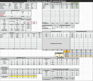
This article looks into an approach that helps the reader visualize how the mud weight (MW), surface-applied choke pressure (SACP) and ECD interact to achieve the desired result. In many instances, MPD is a technique that can leave several questions in the reader’s mind. The approach described in this article shows how to use a single-phase hydraulics macro in Excel to analyze a hole section identified as an MPD candidate.
This simple approach also approximates the optimum MW that should be used to drill the section using MPD. While applying the MPD technique, only the open-hole section is analyzed instead of the whole well, since cased-off sections do not affect well control or formation stability.
In most cases, MPD is applied in a single troublesome section, although sometimes it is applied in multiple sections posing different problems. Quite often, if the equipment is already in place for use on a single well section, MPD proves to be advantageous and is used to mitigate issues on other well sections that is possible to handle by conventional methods but can be handled better with MPD.
Level 1 analysis methodology
This simple method consists of a Cartesian coordinate system where the x-axis relates to ECD (ppg) and y-axis refers to open-hole length in ft. As stated, only the open-hole section will be considered. Therefore, a lateral length of 4,846 ft of open hole will be part of this analysis.
Consider the following data for a well with a tapered drill string:
Well construction data
- 9 5/8-in. casing (8.535-in. ID) landing point at 5,400 ft;
- 7-in. liner (6.276-in. ID) landing point 10,154-ft MD (9,000-ft TVD);
- Liner lap of 300 ft; and
- 6.125-in. open hole. TD at 15,000-ft MD (9,000-ft TVD) (4,846 ft of open hole).
Drill string configuration data
- 200 ft of 4.75-in. BHA. Remainder of pipe is 4 in., 14 lb/ft to top of the liner; and
- Crossover to 5-in., 19.5-lb/ft drill pipe to surface.
Formation/Reservoir data
- 11.3-ppg FP;
- 10.9-ppg PP;
- Window between PP and FP = 187 psi (0.40 ppg);
- Horizontal section inclination is the same (90°) from 7-in. liner shoe to TD (for the purpose of simplicity);
- Geomechanics study has identified this reservoir to be competent over the range of pressures anticipated, so no wellbore stability issues are likely. In some cases, pressure to maintain wellbore stability may represent the lower limit of the operating window and will be substituted for PP. The methodology remains the same; and
- Production history of the area has shown that this reservoir has always been fracture-stimulated. Without stimulation, a drawdown of over 300 psi is required at the sandface to induce flow.
Operator’s problem while drilling
- The reservoir has always been drilled using conventional methods (single-phase fluid using an oil-based mud of 11.5 ppg);
- While drilling, high background gas, lost circulation and, in some cases, small kicks have been experienced in the area; and
- The operator believes that, with 11.5-ppg mud, the wellbore pressure is exceeding the FP value, resulting in wellbore breathing.
Area prognosis
- Per the screening of the area, this reservoir has been identified as an MPD candidate;
- It is believed that the current drilling MW of 11.5 ppg is reaching the value of fracture initiation pressure and later keeping these fractures open with an ECD value aiding in fracture propagation;
- Due to the opening of these fractures, the reservoir is breathing and creates a sequential loss and discharge of the drilling mud. In some cases, gas accompanies the discharge of mud into the wellbore, which is seen in the form of high background gas while drilling;
- Previously, to stop this background gas, the MW was raised, which resulted in more breathing and contributed to more background gas to surface.
Level 1 MPD section analysis
Since MPD is a single-phase fluid operation in most cases, a simple hydraulics calculator can be used to simply approximate both static and dynamic pressures or ECDs without using a software model. The values generated by this calculator will be inserted in the Cartesian graph alongside the PP and FP.
The flow rate used for hydraulics calculation is taken as 260 gpm for a 6.125-in. open hole.
A summary of the calculation for bottomhole circulating pressure (BHCP)/ECD and other hydraulic parameters can be seen in the single-phase hydraulics program shown in Figure 1.
For purposes of simplicity:
- ECD is taken at two points (at 10,154-ft liner shoe and at 15,000-ft TD);
- ECD is calculated via single-phase hydraulics sheet (at liner shoe and TD);
- FG & PP are taken as constant throughout the horizontal wellbore;
- The choice of MWs is dependent on calculating the balanced MW required to control the formation pressure of 5,100 psi. Balanced MW for this case is 11 ppg;
- The drilling MW is 11.5 ppg (historically this is the MW used in this area);
- MPD uses a lighter MW, so three MWs have been selected for the analysis. The MWs are selected on two extremes using a minimum and a maximum value to create a window that will allow selection of an optimum MW; and
- Three MWs are selected, including 11.5 ppg; the drilling MW, with 10 ppg as a mid-level; and 9 ppg to be the lightest MW examined.
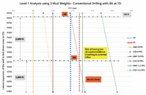
First, the three MWs are plotted on a single chart with PP and FP. Figure 2 shows the effects of these three MWs. Note that the x-axis is ECD (ppg) and y-axis is the lateral extension or horizontal leg of the reservoir in feet. It is evident that the drilling MW of 11.5 is above the FG of 11.3 ppg, creating fractures and resulting in losses while the pumps are running and a flowback of those losses when the pumps are shut down (wellbore breathing).
10-ppg mud
- With the bit at TD, 300 ft of the lateral section just outside the shoe will go slightly underbalanced. The permeability of this formation is low enough that this slight drawdown at the sandface will not result in a significant influx while drilling unless a natural fracture with connectivity is encountered, something which rarely occurs in this reservoir.
- Approximately 2,650 ft of the lateral section will remain overbalanced and below the fracture gradient line.
- Unfortunately, at 13,100 ft, the ECDs will cross the FG line once again, leading to lost circulation and potential flow from the reservoir. The graph shows that almost 2,000 ft of the lateral section will be in danger of crossing the FG line.
9 ppg mud
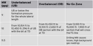
From the graph, it is clear that a 9-ppg MW will be lower than both PP and FP. A low MW like this will require adjustments using a choke that can introduce an SACP on the formation to keep the same ECD at the sandface, both with the pumps running or shut down. This ECD will stay within the window between the FP and PP. Having a low MW also reduces the number of solids/barite, something that could result in higher instantaneous ROPs. ROP is a challenge in this area with the 11.5-ppg MW. Overall results of this analysis is in Table 1.
Analysis using 9-ppg MW as an MPD drilling fluid

Now, let’s see the effect of using a 9-ppg mud system and its relationship with SACP and corresponding ECDs. In order for the well to be drilled at 9 ppg, referring to Figure 2 will allow the engineer to analyze a range of SACP that are required from the shoe to the TD without exceeding the FG.
In Figure 3, using conventional drilling methods, a 9-ppg mud will not overcome the pore pressure of the formation. Figure 3 also clarifies the role of annular pressure loss, which is proportional to the length of the wellbore.
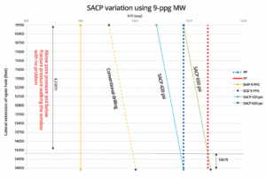
As the lateral length of the well increases, SACP goes to a lower value. This also confirms that the full length of the wellbore during MPD is neither “at” nor “slightly overbalanced to” the formation pressure. In other words, it is wrong to say that SACP can keep a constant bottomhole pressure throughout the length of the wellbore, but it is correct to say that SACP allows one to maintain a constant pressure at a selected location in the wellbore. That location may be at the casing shoe, the toe or anywhere in between. Correct selection of the combination of MW and SACP can, however, often allow maintaining the entire wellbore within the required operating window.
Figure 3 also identifies three spots (or nodes) with their respective SACP values, which will bring them at balance with PP. They are summarized in Table 2.
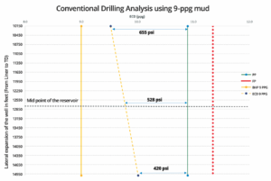
The question is how much of an SACP is required to drill this 4,840 ft of open hole.
From Figure 4, two values of SACP are taken into consideration. Notice that with a lower SACP value of 420 psi, the BHCP at the sandface is lower than the PP, but an SACP value of 650 psi is capable of staying within the window between PP and FP until reaching 14,410 ft. Several other observations can be made from using an SACP value of 650 psi:
- A total of 4,256 ft of open-hole section can be drilled without having any problems. In other words, this will be a classic “walking the window” scenario where ECD is above the PP but below the FP;
- As the open-hole length increases, annular pressure loss also increases, meaning at 14,410 ft, if SACP remains at 650 psi, then the ECD will eventually exceed the FP, causing the final approximately 600 ft of section to suffer lost circulation and a possible influx;
- Point 2 is also an alarm for drilling engineers, as they may have to alter their drilling strategy before approaching the depth of 14,410 ft. For instance, an option of altering the SACP to a value that can bring the resultant ECD lower than the FP and slightly above the PP;
- Lowering the SACP may result in underbalanced conditions near the casing shoe. The value of adjusting the SACP can also be taken off Figure 3, such as a small adjustment of 50 psi is required to bring back the green line (SACP=650 psi) to the left of the FP line. This, in turn, will create a drawdown of 50 psi near the casing shoe, creating a minimal underbalanced condition;
- Note, the flow from any reservoir is a function of drawdown, a record of which can be found in the production history. It may well be true that a 50-psi change in BHCP at the casing shoe will not add any impact in terms of influx, or it might just add a bit of gas, similar to background gas in conventional drilling.
Conclusion
The proposed method demonstrates a simplified technique to perform a Level 1 MPD analysis across a given open-hole section based on a chosen range of MWs. It helps readers appreciate the relationship between SACP and MW and their impact on drilling hydraulics design in reservoirs with a low PP and FP window.
The suggested range of MWs is solely at the discretion of the drilling engineer or the user. A good practice, however, is to take a minimum and a maximum (typically the drilling MW) to establish a window that will allow the drilling engineer to select an optimum MW.
Because MPD utilizes a lower MW, the static hydrostatic head of the drilling fluid will typically be lower than the reservoir pressure at any point, if SACP equals 0. It should also be noted that this analysis does not consider a single MW selection, which ultimately dictates the value of SACP that would be required to keep the well above the PP and below the FP throughout the drilling operation. These graphs are meant to assist drilling engineers in carrying out a Level 1 analysis without the need for exhaustive understanding of the MPD design or relying on vendors. However, detailed design, such as Level-2 study, must be carried out to ensure proper design with suitable selection of MPD equipment (manifold, rotating control device, etc) to allow for a successful job design and execution. DC
Acknowledgements: The author would like to thank Dennis Moore from Marathon Oil, and Lashar Lavenue and Steve Ortiz from Saudi Aramco UPDC for their assistance.


