Vessel selection, lessons learned in using a drillship for temporary abandonment of 15 subsea wells
Drillship edges out light well intervention vessel after operator analysis of multiple technical, commercial factors
By William Liew Sin Yoong, Khalil Mohamed M’bareck, Shahira Emie Lyana Bt Mustaffa and Mohd Hairi Abdul Razak, PETRONAS; Frederic Jacquemin, William Zomerdijk, PACIFIC DRILLING
As the final stage in the oil and gas field life cycle, abandonment and decommissioning (A&D) activities are inevitable and have been increasing. For one deepwater subsea field offshore Mauritania in West Africa, the operator decided to cease production due to depleted reservoirs and the low oil price environment.
This article discusses how the operator selected the drillship to carry out the A&D project, including considerations of the advantages and disadvantages in using a drillship for such operations, as well as the optimization performed on the rig and lessons learned.
Background
It was critical to the operator that the A&D project is cost-effective, compliant with Mauritanian and international legislative and regulatory requirements, follows good industry practices and leaves the seabed and marine environment safe and pollution-free.
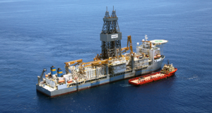
The project encompassed 15 subsea wells, hinged over subsea templates, manifolds, flexible flowlines, umbilicals and risers tied back to a permanently moored FPSO. Fourteen of the 15 subsea wells were located in water depths between 730 m to 830 m. The remaining well was located on an adjacent field in a water depth of approximately 280 m.
The operator decided to carry out the project in two phases. Phase 1 was to consist of temporary well abandonment and FPSO decommissioning and disconnection, and Phase 2 would involve well plug and abandonment (P&A).
For Phase 1, the temporary barriers placement was designed with the end state in mind – the final well P&A. This philosophy and the required contingency plans to ensure successful barrier placement drove the selection of riser-based subsea well intervention over riserless intervention. This subsequently narrowed down the options during the vessel selection process. In addition, the operator considered the potential synergies that could be achieved between Phases 1 and 2 by using the same vessel or drilling unit.
Vessel Selection
It was recognized that selecting a suitable well intervention vessel or MODU would play a vital role in the successful delivery of this project. Phase 1 required a vessel that could handle the completion/workover riser (CWOR) system, well intervention services, equipment and personnel for each temporary well abandonment activity, as well as the contingency options.
The majority of light well intervention vessels (LWIVs) surveyed were not suitable for the scope of work, mainly due to the riser-based requirement. This narrowed the selection to MODUs and a few purpose-built riser-based intervention vessels that were available in the market at the time.
Although not critical in Phase 1, the requirements for Phase 2 operations were also considered in order to create more synergies between the two phases. One of the Phase 2 requirements then further narrowed down the vessel selection to a MODU with dual-derrick capability, which would allow the CWOR system and the BOP to be handled simultaneously
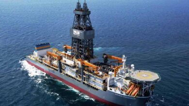
Based on key technical and commercial considerations (Table 1), the operator then chose a sixth-generation drillship to execute Phase 1 of the project; the rig was subsequently lined up for Phase 2, as well. Each of the criteria leading to this final selection is further described below.
CWOR System
Based on the survey conducted, it was found that most of the LWIVs available for riser-based subsea intervention were equipped with a CWOR system and were purpose-built to run that system, ensuring efficiency in the system’s use.
Drillships do not have this advantage, although they do have the flexibility to run and operate CWOR systems, thanks to state-of-the-art machines on the rig floor, spacious moonpools and moonpool decks. On top of that, drillships have the ability to rack back drill pipe risers in stands, which would contribute to better performance in running the CWOR system.
In this project, the CWOR system was provided by the drilling contractor through rental services from another service contractor. Due to the potential requirement to handle H2S-contaminated returns, the 6 5/8-in. drill pipe risers and 2 3/8-in. annulus tubing had to be made from NACE MR0175-compliant material. These were also sourced by the rig contractor.
Drilling BOP
Only drillships could provide a drilling BOP, which was not available on LWIVs. This limited the ability of LWIVs to perform certain operations required in well P&A, such as section milling and annulus cementing through the perf-and-wash technique, which would be required in Phase 2.
Dual Derrick Operations
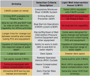
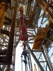
Many drillships have dual-derrick operation capability to handle and run the CWOR system and the BOP simultaneously. This could not be done by LWIVs. With this advantage, in Phase 2, the operator could latch the BOP onto the wellhead within a short duration of time after unlatching the subsea Christmas tree using the CWOR system. This was one of the criteria leading to drillship selection in this project.
Rig Up/Down of Well Intervention Pressure Control Equipment
Some LWIVs have a built-in tension frame or coiled-tubing lifting frame, which would allow both wireline and coiled-tubing pressure control equipment to be rigged up side-by-side simultaneously. This configuration would allow for easy change-out between wireline and coiled tubing during operations. Drillships do not have such a feature.
Ability to work in 280-m and 830-m water depths
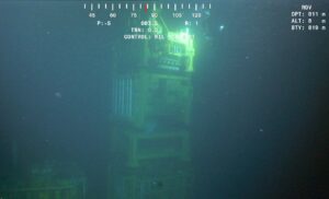
Both drillships and LWIVs are able to work in the expected water depth range for this project. The shallowest well, in 280 m of water, required additional evaluation of local metocean conditions to ensure the operability of the dynamic positioning system and sufficient response time in the event of an emergency disconnect.
Deck Space
There were notably more deck space available on drillships than on LWIVs. Drillships’ spacious deck area would allow for flexibility to store and handle multiple well intervention services equipment at the same time, without heavy reliance on supply/support vessels. Further, the specific drillship that was selected had a dedicated well test deck and built-in burner boom, which enabled safe installation of flowback equipment on the rig to handle returns from the well.
ROV System
Both drillships and LWIVs can easily accommodate two remote-operated vehicles (ROVs). Some LWIVs have the additional advantage of having a purpose-built ROV hanger and control room.
Heave-Compensated Crane
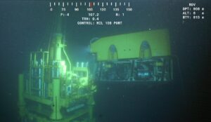
Most of the LWIVs considered were equipped with heave-compensated crane for subsea intervention work, while only some drillships have this feature. The drillship that was ultimately selected for this project did not have a heave-compensated crane. However, its dual-derrick capability was optimized to overcome the challenges of not having a crane for subsea work. Slings and ROV hook assembly were run on drill pipe through the auxiliary derrick for the purpose of subsea equipment pulling and retrieval during Phase 1.
Daily Charter Rate
The daily charter rates (DCRs) of LWIVs were generally lower than those for a sixth-generation drillship. Nevertheless, during the low market environment when Phase 1 of the project was carried out, the drillship DCR was attractive enough to be compared with LWIVs.
In order to create a more commercially attractive comparison, the operator also required the integration of additional critical services into the rig contract, such as provision of the CWOR system, 6 5/8-in. drill pipe riser and 2 3/8-in. annulus tubing, two ROV systems, an H2S cascade system and one supply vessel.
The combination of these services under a single point of accountability led to cost optimization and operational efficiencies. On top of that, the contractual term of “one down, all down,” referring to nonproductive time (NPT) of the whole package if any single component is down or malfunctions, incentivized multiple service providers to work better as a team to ensure high equipment uptime.
The commercial attractiveness of the drillship was further improved by the inclusion of a priced option under a predetermined DCR for Phase 2 of the project.
Challenges and New Opportunities
LWIVs have been widely used in the industry for subsea well interventions. Although there are limitations in their capability, specially built LWIVs have proven to be cost effective and efficient in selected subsea intervention jobs.
In contrast, such a provision of integrated subsea well intervention services was the first for the rig contractor in this project. Three main risks were identified:
1. The integrated commercial model of “one down, all down” created great NPT risk for services outside of the rig contractor’s typical expertise.
2. The contractual structure where the rig contractor acts as the integrator for many services, such as the CWOR system and ROVs, had some gaps in the contractual terms between operator/rig contractor and rig contractor/service companies. This led to increased commercial and contractual risks.
3. The short time frame from contract award to commencement of operations generated an execution risk.
The challenges were overcome and brought new learnings and opportunities to the rig contractor. During the project execution, the rig contractor developed standard internal procedures to ensure good oversight and supervision of the CWOR system and ROV services under their scope of provision. This greatly reduced downtime and enhanced the reaction time to any unexpected failures.
Further, communication between the rig contractor and its subcontractors was improved to allow direct interface between management of both sides. This enabled timely management support to resolve any operational issues on the rig.
Additionally, a new Well Intervention Team was established within the rig contractor’s organization. The team recorded all lessons learned and procedures during the execution of Phase 1.
The knowledge captured within the rig contractor’s organization will enhance its performance in Phase 2 of this project, as well as future deepwater subsea well intervention opportunities.
Lessons Learned and Optimization Opportunities
As this was the first deepwater subsea temporary well abandonment for both the operator and rig contractor, valuable lessons were learned and recorded, and optimization opportunities were identified during execution of Phase 1.
Some of the lessons learned were incorporated into operating procedures, which then improved performance of Phase 1 by taking the full benefit of a learning curve over the 15-well campaign. Other lessons learned and optimization opportunities were also captured for implementation in Phase 2 or other similar operations in the future. This section discusses only selected lessons learned involving the rig, ROV and CWOR system.
One notable challenge was encountered during the removal of subsea Christmas tree caps, with hydrate formations within the tree cap restricting the opening of the cap. The ROV in Phase 1 was equipped with an intervention skid for pumping glycol. However, methanol is the best fluid to dissolve hydrates, yet it could not be used on the rig due to the lack of a proper setup for safe storage and handling.
Fortunately, the hydrate blockage was cleared after continuous pumping of glycol from both production and annulus ends of the tree cap. This could be improved in similar operations on a drilling rig by ensuring there is a suitable setup to handle and store methanol.
Additionally, it was recognized that ROV operations to clean the Christmas Tree re-entry hub could be improved by using a fit-for-purpose hub-cleaning tool instead of high-pressure jetting. The hub-cleaning tool was subsequently fabricated and utilized in Phase 1 to reduce rig time in cleaning the re-entry hub.
On the same ROV operations, it was found that the ROVs had to return to surface to collect additional beacons during beacons positioning at new well locations. This could be avoided in the future if more hooks on the ROV cages were allocated, so both ROVs could carry all eight beacons down at the same time.
Another challenge identified was related to pressure testing. Many of the functions and pressure testing on CWOR system and wireline or coiled-tubing pressure control equipment could be done offline on the drillship, which contributed to rig time saving. Nonetheless, there was still a significant amount of time spent on pressure testing due to leaks on the surface lines. The amount of Chicksan iron piping and low-torque valves on the surface line further complicated the situation.
For future operations, integration of the well services high-pressure pump with the CWOR system could be done through a dedicated test manifold.
Results
Phase 1 of this first deepwater subsea temporary well abandonment for the operator and rig contractor was safely and successfully completed. Throughout the project execution, there were zero fatalities, zero lost-time injuries, zero major fires and zero major losses of primary containment.
Improvements in operational performance were seen throughout the 15 wells. The temporary abandonment of the first well took approximately 24 days to complete, while two of the final few wells took only approximately four days to complete.
Overall, the project was completed in 137 days, 22 days ahead of the planned time and below AFE cost. Such performance was enabled by constructive engagement and cooperation among operator, rig contractor and all service partners. DC
This article is based on a presentation at the 2019 IADC Wells Technology Conference, 1-2 October in Kuala Lumpur, Malaysia.

