Computer vision system developed to optimize tripping operations
Pilot program on jackup shows image sensor technology can provide accurate, optimized height setpoints for pipe-handling machines
By Ylva S. Vintervold, Marianne Holmstrøm, Hugo L. Rosano and Stephen Forrester, National Oilwell Varco

Optimization and automation of traditional rig-floor drilling processes are eliminating manual procedures that rely heavily on the individual, replacing conventional methods with automatic and intelligent systems. National Oilwell Varco (NOV) designed Strix vision solutions in response to demands in process automation, optimization and enhanced safety. These solutions provide increased efficiency and safety through the use of imaging sensors and computer vision techniques. Objects are remotely identified and the image results are analyzed to accurately measure and track such objects on the rig floor.
During tripping operations, the iron roughneck must be moved to the well center from a parked position, and its dolly must be positioned vertically in such a way that it can accurately clamp onto the lower part of the tool joint. The tool joint, depending on where the hoisting system stops, can be located at various heights, leading to an inefficient system of movement based on iron roughneck trajectories. In addition, the column racker uses a conservative trajectory for pipe stabbing, which can also be optimized once the specific position of the connection is known.
The Strix stickup height detection (SHD) technology, which is independent of machine models, addresses these issues by providing an accurate height setpoint for pipe-handing machines during drill pipe and casing trip-in sequences.
SHD vision technology
Conventional approaches to positioning the iron roughneck generally involve the operator manually verifying height and inputting coordinates. As experience can vary significantly from person to person, there is no guarantee of individual performance. Alternatively, machine-mounted sensors require positioning the iron roughneck approximately 30 cm below the actual pipe. The incorrect assumption that pipe box length is fixed further complicates the issue, leading to more inefficient iron roughneck trajectories and forcing the operator to use additional equipment and/or sensors. Once the stickup height is available in the system, various machines can optimize their trajectories for connection operations.
By using an automated vision system, sensors don’t have to be installed next to objects. The system measures the height of pipe remotely, with feedback to the control system yielding automatic and optimized machine trajectories. Initial focus has primarily been placed on iron roughneck motion, but the height setpoint could also be used by the column rackers to shorten the vertical travel for connection stabbing.
Challenges in developing such a solution included incorporating the full variety of possible scene conditions on the drill floor, including all possible pipe types and appearances, machines in the background and fluctuating conditions, into the developed algorithms. Because it is difficult or even impossible to control these factors, the solution had to be significantly different from one that could be implemented in a factory or workshop, where conditions are manageable.
Typical image-processing techniques could not be used because of the inability to control these factors, and commercial products are not robust enough to cope with them. As such, NOV developed and tested a computer vision system tailored to drill pipe and casing connections.
System design

The system is composed of several parts. First, a high-performance digital camera package is installed in a remote, static position with a clear line of sight to the main or auxiliary well center, depending on where pipe connections are made. The camera, which is mounted at least 1 m above the maximum possible stickup height, does not obstruct the operator’s field of view or interfere with machine operation. The camera is active when the control system requests a measurement, whereupon the camera streams the images to an industrial PC (IPC) configured specifically for image processing.
This IPC is an integrated part of the drilling control network, synchronizing and providing measured information for the pipe connection to machines and other controls systems. Each machine is still controlled by its own programmable logic controller (PLC).
During installation, the camera is calibrated by using an intuitive tool to estimate the relationship between pixel and rig coordinates. Once accomplished, the real position of objects can be inferred from the pixel coordinates. The stream from the camera is continuously analyzed, with the system setting a region of interest in which it searches for distinguishable pipe features while ignoring background noise.
The sensor and algorithms normalize and compensate for variations in the challenging drill-floor environment, with the system defining a representation of drill pipe geometry to allow the top of the pipe to be detected. Motion or vibration of the vessel does not affect the solution, as the camera’s position is fixed relative to the well center.

The measured height is distributed to machines in the control network and other control systems, which use it as a setpoint. In addition, various internal criteria are calculated and brought together by the system to enable creation of a confidence metric, which represents the system’s confidence in its own measurements. This metric is sent with the height setpoint to the receiving control systems and can be used by both the operator and the control systems as a safety barrier. Additionally, the image stream, with the detected height indicated, can be displayed on the driller’s control screen.
As part of the development and validation process, the system has been installed on a jackup, where logging of results from the system and relevant machine data and images are enabling data processing and analysis. This takes place offline to allow validation of the results and additional development to be performed before closing the loop. The pilot program has been active for more than eight months; testing and results are detailed below.
Testing
Test procedures were developed and implemented to analyze and validate performance. The computer vision system was analyzed through offline processing of image snapshots from the offshore pilot project using 1,085 images that represented expected image quality and had sufficient ambient light. The images captured changing weather conditions, varying pipes and casing appearances and heights, shifting backgrounds, and increasing amounts of dirt as time passed. The analysis was conducted by running the vision system for each snapshot in turn (“experiments”) and logging results, which were then processed to calculate statistics.
The success or failure of the system depends on the accuracy of the measured height setpoint and on the system’s calculated confidence in its own measurements. For an experiment to be successful, the system must properly detect pipe height at an established confidence threshold.
Achievable efficiency and consistency improvements for the iron roughneck trajectories were investigated. Logs containing the motion of relevant machines were available, with a total of 3,416 trip-in sequences isolated from the rest of the data for analysis. Although iron roughneck motion data using the vision height measurement in a closed loop was not available due to the nature of the pilot program, theoretical performance of using the vision system was calculated. NOV’s Drilling HIL Simulator (DHS), configured for the same rig, was used to further investigate the results.

The success rate achieved by the computer vision system is shown in Table 1. Almost all of the snapshots (98.71%) gave the correct height output and a confidence above the level where the measurement can be trusted. False positives represented just 0.09% of the experiments. Such issues, while extremely unlikely to happen, can be dealt with by proactively employing additional safety barriers.
Results
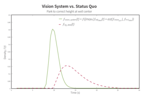
Based on analysis of pilot rig data and statistics for the computer vision system, inclusion of the height setpoint in trip-in operations would result in average time savings per connection of 4.23 seconds for the pilot rig. The height detection system outperformed the status quo, particularly in cases where the combination of image processing and height correction times is the limiting factor, rather than horizontal travel (Figure 1). The system takes advantage of time spent moving the iron roughneck horizontally to simultaneously move the dolly to target height.
Traditional approaches perform the whole height correction after arriving at well center. An efficiency improvement of 26.2% can be achieved by moving the dolly directly to target, eliminating 4.23 seconds from the 16.1-second mean time per connection. Additional efficiency can be achieved for such sequences if the system is set to begin processing prior to beginning horizontal motion and by increasing machine speeds according to data sheets.
Increased consistency is another advantage of using an automated system. In Figure 2, which shows recorded times to move a given vertical distance on the pilot rig, such times vary significantly for the same height. The line shown along the lower end of the scattered dots represents the maximum dolly speed achieved on the rig. Using the computer vision system enables the time to correct a given height discrepancy to follow the lower line, which is a function only of machine speed and distance to move. With the vision system, the dolly can be moved directly to the correct height, avoiding problems inherent in the manual approach, such as overshoots and the need for continuous monitoring.
NOV’s DHS, configured for the offshore rig on which the pilot program took place, was used to validate the efficiency-improvement hypothesis. The simulator analyzed how the vision system would achieve the desired efficiency results by allowing the iron roughneck to move directly to an accurate height target. Maximum machine speed on the pilot rig’s iron roughneck was used during the simulation. Two conventional approaches were tested for comparison – the manual approach and an existing automated sequence – and the machine was allowed to move in both directions simultaneously to simulate iron roughneck motion using the vision system. Machine code as implemented on the rig was used, and an accurate height setpoint was provided.
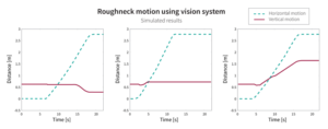
The simulated results validate that when using the vision system, no additional time is required for height adjustments after the iron roughneck has reached the well center. Figure 3 provides more detail on the results of three simulations using an accurate height setpoint.
The left plot shows a setup where target height was lower than default starting position. Due to mechanical restrictions in the iron roughneck frame, downward motion is stopped until the torque wrench frame is extended. Despite this, the roughneck reached target height when arriving at the well center.
The center plot shows a sequence where a 15-cm upward adjustment was necessary to move from initial to target height. As the height is adjusted during horizontal motion, it is correct by the time the iron roughneck arrives at well center.
The right plot shows a sequence in which the target is approximately 1 m higher than the default position. Despite this, by using the vision system, the roughneck height is still correct when the target arrives at well center. All three sequences required only the time needed to reach the well center.
Reducing connection times by 4.23 seconds per connection over the course of an example rig’s standard operational time would result in approximately 16 hours saved per year. Optimization of racker stabbing, using the same setpoint, can save an additional 2 seconds per connection. Assuming a daily rig rate of $414,000, this would translate into savings of more than $391,000 per year.
Future development
NOV is currently planning to launch Strix fingerboard latch detection (FLD) to ensure safe racking operations with tubulars in the fingerboard area. Drop incidents and equipment damage are among the most serious pipe-handling challenges in modern drilling systems. Many of these challenges stem from the lack of individual latch-position monitoring. Strix FLD would provide real-time state condition (open, close) of latches based on images captured from cameras mounted on the racker, thus removing the need for personnel to visually confirm latch status. The system, which has undergone extensive testing, is being deployed on an offshore rig for validation. DC
Strix is a trademark of National Oilwell Varco.
This article is based on SPE/IADC 184664, “Tripping Operations Optimized Through Closed-Loop Vision Technology,” presented at the 2017 SPE/IADC Drilling Conference, 14-16 March, The Hague, The Netherlands.


