Onshore drilling & technology briefs
Automated rig aims to improve efficiency, safety with hands-free tripping, pipe handling
By Katie Mazerov, contributing editor

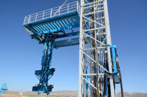
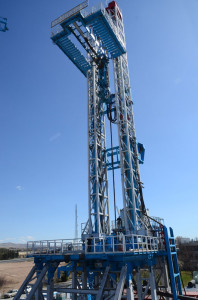
An Italian company has built an automated drilling rig that replaces the drawworks with hydraulic cylinders and performs hands-free pipe-handling, monkeyboard and drill floor functions with built-in redundancy. Only one individual is required, in the driller’s cabin, to supervise operations, as well as a mechanic and a mud engineer.
The Genesis BQ Automated Hydraulic Drilling Rig was developed for a range of oil and gas drilling, including unconventional formations, as well as deep geothermal wells. It has been designed in six sizes from 200 to 700 metric tons and 1,000 to 3,500 hp, according to Walter Bagassi, President of B Robotics W SRL.
The BQ 400, which comes with 400 metric tons of static hookload, is being field-tested on a geothermal well for ERG in Gölbaşi, Turkey, 30 km from Ankara. A smaller, 250-metric ton model is being built in Italy for Italian drilling contractor Hydro Drilling, with delivery expected at the end of October this year. Mr Bagassi notes that this newbuild includes an extended agreement for Hydro Drilling to order one rig per year for the next five years.
The rig can drill in automated mode or manual mode. Designed with six pipe containers, each holding 104 sections of 5-in. pipe, the BQ 400 can drill to 5,730 m (18,830 ft) in either mode. With additional pipe containers, the rig can drill to a maximum total depth of 8,711 m (28,579 ft). Each pipe container enables the rig to drill an additional 957 m (3,139 ft).

The BQ 400 is engineered to accommodate up to 14 pipe containers, stacked next to each other, with seven containers on each side of the pipe/casing-laying machine. The containers feed the pipe/case-laying machine, which runs casing in the hole without the need for a crane or additional personnel.
“The innovation is in the rig itself, which can drill to a specific depth hands-free, taking people off the monkeyboard and away from the rotary tongs, where most accidents occur,” said Mr Bagassi, a petroleum and aeronautical engineer who began working on the design in 2000.
“The system for loading pipes below the top drive is fully automated. The driller supervises the operation without touching anything, letting the rig drill on its own to a specific depth.”
Apache Corp has looked at the Genesis rig design and commended its innovation. “The hands-free design that facilitates the critical functions of faster, more efficient tripping and pipe-handling by taking people out of harm’s way makes this a smart, intelligent rig that is energy-efficient and quieter,” said Lance Spencer, senior drilling advisor, Worldwide Drilling Group for Apache.
Hydraulic cylinders
Central to the design is the replacement of the drawworks with long-stroke hydraulic cylinders installed on each side of the mast frame, Mr Bagassi explained. The cylinders face upwards and can lift up to 1 million lb by pulling, instead of pushing, on the piston rod, eliminating dead-end load. “The hydraulic cylinders move the top drive up and down, allowing the rig to trip in and out three Range 2 drill pipes on its own,” he said.
The cylinders are activated by heavy-duty gear pumps controlled by variable frequency drive (VFD) modules. Conventional hydraulic rigs use variable pumps equipped with an inner disc to increase or decrease fluid flow to pump pistons, Mr Bagassi said. The pumps require multiple filters to keep fluid clean. Gear pumps can operate when oil is less than completely clean and can function with water and additives.
Redundancy allows the rig to continue working if a component fails, even in remote operating environments. “We duplicated all the sensors and key equipment,” Mr Bagassi said. “If only one of the 12 pumps is operational, the rig can continue drilling.” The rig has two top drive motors, four hydraulic cylinders, two electric control panels, two hydraulic power pack units interchangeable with 12 hydraulic pumps, 12 independently operating VFD units, two rig sensors and two central processing units each on the monkeyboard, tubular handling and working floor electrical panel.
The rig is also capable of pad drilling and has 360° walking capability. It can operate in environments ranging from -50° to 55°C (-47° to 131°F). By eliminating the drawworks, the rig is quieter than conventional rigs. The lightweight design with fewer components also requires 40% fewer standard trailers for transportation. The rig also can be installed on an offshore platform.
“Our goal over the next three years is to expand remote operating distances and develop a remote-controlled rig that can drill without any personnel,” Mr Bagassi said. “With dedicated programming and cameras, we can now control tripping operations 100 km (62 miles) from the operation.” The company is also developing tools to facilitate drilling with casing and slips that can be automatically configured from 23 to 3 ½ in. without any other intervention.
California’s SB4 provides framework for well stimulation regulations
By Lauren Wolfson, editorial assistant
Well stimulation operations in California have reached a standstill with the recent passing of Senate Bill 4 (SB4), which sets forth regulations on hydraulic fracturing and acid matrix stimulation operations in the state. Rock Zierman, CEO of the California Independent Petroleum Association, stated that permanent SB4 regulations will go into effect in January 2015, although interim regulations already went into effect in December 2013. The new rules require operators to submit various applications and information to California’s Division of Oil, Gas and Geothermal Resources (DOGGR), but confusion around various aspects of compliance have led to a significant delay in permitting.

While many US states, such as Illinois and New York, already regulate hydraulic fracturing, SB4 moves beyond that to encompass all well stimulation treatments, with requirements for well integrity testing, landowner notification, groundwater monitoring and more. Operators must give 30 days’ notice to landowners and the DOGGR to receive a permit for any well stimulation treatment. They also must perform well integrity testing prior to and after stimulation, as well as disclose all chemicals used in the well stimulation treatment. If the stimulation is to take place in areas where there are usable water sources, then a groundwater-monitoring plan is required.
The state of California is currently conducting an environmental impact report (EIR) along with a statewide scientific study on hydraulic fracturing and its environmental effects. SB4 requires the results of these two studies to be accounted for in the permanent regulations as they are both intended to review potential risks of fracturing. “(The studies are) largely going to be a gathering of publicly available information and a review of all of the different potential environmental risks with hydraulic fracturing,” Mr Zierman said. The studies are intended to educate the public, as well as California lawmakers, on hydraulic fracturing and are expected to be completed by July 2015.

However, that date of completion is causing some concern since the permanent regulations are supposed to go into effect earlier that year. “One of the problems with the bill was it said the permanent regulations have to be in effect January 1 of (2015), and the EIR wasn’t going to be done until July 2015,” Mr Zierman explained. He noted that the industry is now in discussions with California Gov. Jerry Brown to harmonize those dates. Clarification of the regulations will continue until their implementation in 2015.
The groundwater-monitoring plan has also caused concerns and delays for operators in California. Operators are being required to submit a plan if they are beginning well stimulation within areas that have “protected water.” Mr Zierman explained “SB4 envisioned that the regional water boards would, over the course of the next 12 to 18 months, come up with the criteria on what should be in that monitoring plan,” but during this waiting period, operators do not have a clear definition of protected water or criteria for the groundwater-monitoring plan. As a result, the industry has essentially been put on pause, with no movement on applications for well stimulation. “Since January 1, nothing was approved until I believe (mid-March), and that was just for one company for permits in areas where there is no protected waters.”
As industry begins to deal with SB4 and its various impacts on operations, environmental activists continue their efforts to permanently ban hydraulic fracturing. In Los Angeles, for example, the city council is now considering a moratorium on fracturing operations. “The L.A. City Council is currently seeking to ban all hydraulic fracturing, well stimulation and oil production within the city limits,” explained Rhett Winter, IADC Director, Onshore Operations. “They also have stated future intentions to possibly push the ban to L.A. County. This could have a significant negative effect on both our members that operate in the area, and the city economy declining due to lack of oil production.” Concerns about the possible ban has already led some operators to consider moving operations to areas outside of the city but within Los Angeles County, Mr Winter said.
Bill Tanner, IADC Vice President, Government & Regulatory Affairs, suggested that the industry work to actively stay engaged and informed with both SB4 and the L.A. City Council actions. “They should continue to monitor the regulatory process for future impacts to oil and gas operations, and they clearly need to understand what their obligations are under the new rules and regulations,” he said.
Mr Tanner noted that, despite the current confusion and delays, the outlook for the industry in California remains positive. “Once the regulations are understood, our members can adhere to them and abide by them and have some certainty that they know what the rules of the road are.” The new regulations are not meant to impede operations but rather function as a “statewide framework for hydraulic fracturing and well stimulation activities,” he said. “I think that it provides certainty and finality in that process.”
Wash bay technology reduces environmental footprint, water use
By Katie Mazerov, contributing editor
A system that recycles the wash water used to clean industrial vehicles is being installed on or near oilfields as a way of reducing the environmental footprint and water use. The wash bay, developed by Riveer Environmental in South Haven, Mich., has been deployed in hundreds of remote locations globally, including US and Canadian oilfields. The equipment can be installed as a permanent facility or as a mobile system by assembling steel wash racks with retrofitted shipping containers that house the filtration systems, said Justin Wilkins, the project engineer who designed the system.
The wash bays use various methods for collecting water, mud and heavy solids that come off the vehicles, including in-ground conveyors that use sloped concrete floors to encourage drainage. Solids also can be collected in side-troughs that dump into sump pits or trenches that can accommodate skid steer loaders, or bucket loaders, for removing collected solids. Where concrete is not practical, such as mobile units, fabricated heavy-duty steel wash racks with conveyors and undercarriage sprayers are used.
Recently, a drive-through wash bay with an in-ground conveyor trough was installed for Brice Equipment Rental in Deadhorse, Alaska. On the North Slope, the cost of importing and/or recycling water is especially high. “In this part of Alaska, it costs roughly $600 every time water is dropped off and $1,400 whenever water, including sewage, is pumped out,” Mr Wilkins said.
The in-ground conveyor was modified to meet the depth restrictions for excavation into the fragile tundra. “Due to excavation limitations in Alaska because of the permafrost, we had to provide a way of removing the solids without digging into the ground,” he explained. “The conveyor was the ideal solution.”
In Deadhorse, vehicles encrusted with snow-packed mud and oil residue from drilling sites are cleaned with a pressure washer that sprays 140° water at 3,000 psi. Designed with two pressure washer guns, a water cannon and an undercarriage sprayer, the system uses 60 gallons of water per minute. After collecting the wash water in the trough, the system recycles it through multiple stages of filtration for continued use.
Water is transferred from the trough into a settling tank, where a spin-down separator, using centrifugal force, forces solids toward the bottom and purges them from the separator. The underground conveyor, meanwhile, moves the solid material into a hopper.
Following this first filtration, the water then moves to a 450-gal settling tank, equipped with an oil skimmer and oil-coalescing media to attract pollutants. Remaining solids are purged out of the tank into a backwash filter and de-watered to lighten the load. Meanwhile, the liquids in the tank are pumped through a media filter and a bag filter, ending up in a storage tank for reuse.
A US operator has installed a Riveer system at its facility in the Utica Shale play in Ohio, and an oilfield services company has built three systems in Ohio, Darlington, Penn., and Midland, Texas. Systems also have been installed in oilfields in Alberta, Canada. Mobile units, which are being used by the US military in remote areas of Afghanistan, include several steel wash racks assembled into a 49-ft-long pad for filtering and recycling the water.
MPD/UBD successfully drills sidetrack after 6 failed conventional drilling attempts
By Joanne Liou, associate editor
In the Brookeland Field in East Texas, conventional drilling methods failed in six attempts to drill a “straightforward” horizontal wellbore. The original well had surface casing installed at approximately 3,500 ft. Intermediate casing with a downhole deployment valve was run to begin drilling the lateral at 11,185 ft. “The original plan was to do underbalanced drilling (UBD) with this well. They drilled to 14,840 ft, and at that point, they ran a survey and found out they were crooked,”George Medley, Executive Vice President, SIGNA Engineering Corp, explained. The operator then decided to drill a sidetrack, but six attempts to do so failed using conventional drilling techniques. SIGNA was then brought into the project to drill the sidetrack using managed pressure drilling (MPD) and UBD, Mr Medley said at the 2014 SPE/IADC MPD and Underbalanced Operations Conference in Madrid on 8 April.
Click here for more on MPD/UBD sidetrack drilling.
GlobalData: China on track to meet 2015 shale gas production goal, but 2020 target remains challenging
Recent production surges and developments by major state-owned exploration companies show promise for China to meet its 2015 shale gas production goal, but its ambitious 2020 target remains distant, and a shale gas ecosystem development has proven sluggish, research and consulting firm GlobalData. The central government is, therefore, determined to reform the industry further with a series of policy updates, in its push to achieve shale gas commercialization, Howe Wang, Upstream Analyst for GlobalData, said.
Based on non-residential city gate pricing and financial incentives expected to be set by the Chinese government, GlobalData evaluated one of China’s most promising shale blocks, known as Sinopec’s Fuling project, and calculated a 7.1% internal rate of return and a break-even price of $7.77 per thousand cu ft.
However, according to Mr Wang, a combination of political, technical and financial issues are impeding further development of China’s shale gas industry. While recent policy updates include enhanced financial incentives for shale gas production, existing resource and infrastructure monopolies remain intact and have had a particularly detrimental effect.
“The majority of China’s premium shale blocks are still closed to foreign gas producers, while national oil companies possess a monopoly over gas pipeline systems. This discourages competition, constrains market participation and hinders significant advances in exploration and technical knowledge,” Mr Wang said.
He noted that the need to fuel China’s fast-growing energy demand is pressuring the government to accelerate domestic shale gas development. As a result, more foreign collaboration is being facilitated to incentivize various investment bodies to enter the market, and ambitious 2020 production goals of 5.8 billion cu ft/day (bcfd) to 9.7 bcfd have been set.
However, “while large-scale production, comparable to American levels, and a dynamic shale gas industry still appear to be distant prospects in China, a robust development plan for the next two years shows encouraging signs of achieving the Ministry of Land and Resources’ goal of 630 million cu ft/day in 2015.”


