Tubular fracturing: Pinpointing the cause
Improper heat treatment can trigger temper embrittlement in oilfield tubulars
By Srinivasa Koneti, Samit Gokhale, Thomas Wadsworth, T.H. Hill Associates
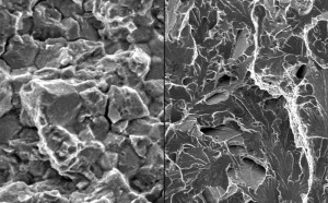
Brittle fracture of oilfield tubular components can occur due to the material having low fracture toughness – such material often presents low Charpy V-notch (CVN) impact energy values – or from exposure of the material under load to certain corrosive operating environments. A brittle fracture can show characteristics of transgranular or intergranular cracking when analyzed through a scanning electron microscope (SEM).
Intergranular cracking is the cracking or fracture that occurs at and along the grain boundaries of a metal. It is characterized by triple points, rock-candy or a faceted appearance when the fracture is analyzed through SEM. Figure 1 shows a typical example of an intergranular fracture on the fracture surface of low carbon steels.
Transgranular cracking is the cracking or fracture that occurs through or across the crystals or metal grains. It is characterized by cleavage steps, river patterns, feather markings and tongues when the fracture is analyzed through a SEM. Figure 2 shows a typical example of a transgranular fracture on the fracture surface of low-carbon steels.
Intergranular cracking is often the mode of fracture that occurs when tubular components are exposed to environmental conditions that contain aqueous H2S. Such failures promulgate the notion that detection of intergranular cracking morphology on fracture surfaces is confirmation of failure through sulfide stress cracking (SSC) or hydrogen embrittlement, even when no evidence exists for exposure to H2S or a source of nascent hydrogen.
Study of intergranular cracking related failures has shown that such failures can occur not only when the component is exposed to nascent hydrogen but can also be caused by temper embrittlement of the material resulting from improper heat treatment.
Temper embrittlement typically occurs when carbon or low-alloy steels are held at or slowly cooled through the temperature range of 375°C (705°F) to 575°C (1,065°F) during the tempering process. If the steels are tempered or slowly cooled at these temperatures, the material shows brittle characteristics (loss of impact toughness).
Steels that have experienced temper embrittlement can be restored to their original or expected toughness by heating (tempering) to 600°C (1,100°F) or above, followed by rapid cooling to below approximately 300°C (570°F).The fracture surface of a material with low CVN impact energy values (brittle material) would normally show transgranular signatures when analyzed under a SEM, whereas a ductile material affected by environmental attack, such as hydrogen embrittlement, shows intergranular separation at grain boundaries.
However, brittle fracture of a material that undergoes temper embrittlement also shows signs of intergranular cracking. Examination of the fracture surface of a component that has undergone temper embrittlement can present intergranular or mixed mode of intergranular and transgranular fracture morphology.
Case studies of Temper Embrittlement Failure
Case 1 – South Texas, onshore US
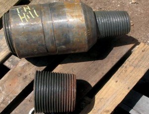
In March 2009, while making up the pin connection (6 5/8-in. reg) of a saver sub, the pin connection on the sub failed. The operator reported that the saver sub was procured new and was in service for three days before the failure occurred.
Based on the appearance of the fracture surface, the proximate cause of the failure was readily recognized by the drilling engineer as a brittle failure. To confirm the failure mechanism, the failed sub was sent for failure investigation.
Case 2 – East Oklahoma, onshore US
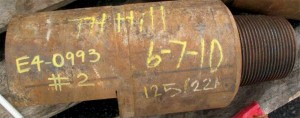
In May 2010, while making up the pin connection (6 5/8-in. reg) of a saver
sub, the pin connection twisted off. Based on the fracture surface morphology, the failure mechanism was identified as a brittle fracture with rapid crack propagation. To confirm the cause of the failure, the failed sub was sent for further investigation.
Case 3 – Northeast Trinidad, offshore
In April 2010, the operator was in the final stage of drilling a horizontal well that entailed the pullback of the 36-in. production pipeline. While pulling back drill pipe joint No. 90, a 7 5/8-in. reg pin connection on a sub that fastened the 42-in. hole-opener to the 500-ton swivel failed downhole.
The attached fractured sub was pulled out, and the mating portion of the sub was not recovered by fishing and subsequently resulted in losing the well. Based on the appearance of the fracture surface, the proximate cause of the failure was identified as fatigue, followed by a brittle fracture. To confirm the failure mechanism, the failed sub was sent for investigation.
Metallurgical Analysis of Failed Subs
Metallurgical analysis of the fractured pin connections on the subs was performed to identify the cause of the failure and the factors that contributed to the failure. To differentiate the fractured pin connections of the subs, the subs will be referred to as:
C1: Sub from Case 1
C2: Sub from Case 2
C3: Sub from Case 3
Visual Examination
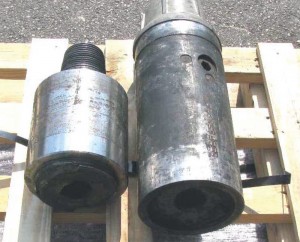
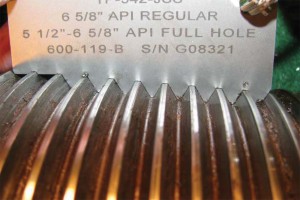
The fractures of all the pin connections were located in the last engaged threads of the pin connections. The last engaged threads of a connection experiences higher stresses and stress concentrations compared with the rest of the connection, making these threads susceptible to cracking. The as-received condition of the failed subs is presented in Figure 3. The C3 sub was received after initial metallurgical testing was performed by another lab. A portion of the sample that was used for previous testing was missing.
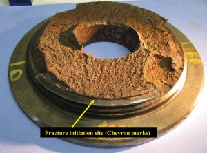
The overall appearance of the fracture surfaces on the subs was flat and oriented perpendicular to the sub axis. The fracture on C1 and C2 exhibited a grainy texture and “chevron marks” that point toward the initiation site. This is typical morphology for brittle cracking (Figure 4).
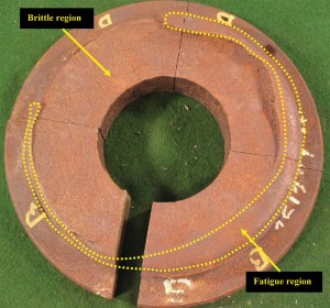
The fracture on C3 exhibited a small fatigue region (approximately 5%) that was followed by brittle fracture. The fracture surface also had the grainy appearance (Figure 5). All three fracture surfaces present a minuscule shear lip, which is also typical of a brittle fracture. Note that the missing material was used for testing during previous investigation.
A thread profile analysis of the failed pin connections of C1 and C2 was performed to check for stretched threads, but no signs of such were observed. This gave further evidence that the pin connections on C1 and C2 failed in a brittle manner and not through ductile torsional/tensile overload.
Material Testing
Material testing of the failed subs was performed to verify compliance with API Specification 7-1 and Standard DS-1 and to determine if improper material properties contributed to the failures. Tensile tests, chemical analysis and CVN tests were performed on the failed pin connection material of the subs.
Tensile strength and yield strength met the minimum requirements specified in API Specification 7-1 and Standard DS-1 for sub material. However, the CVN impact energy values did not meet the minimum requirements specified.
Typically, for the type of chemistry used, CVN values correlate well with fracture toughness. Low fracture toughness makes the material notch sensitive and typically results in predominately brittle fracture.
This indicates that the heat treatment processes were not performed properly to achieve the correct mechanical properties on the subs.
With temper embrittlement, generally, there is no detectable drop in expected yield strength, tensile strength and percent elongation of the material. A drop in the CVN values is often experienced.
In cases of extreme embrittlement, there may be a drop in the percent reduction of area. The material test results obtained on the failed subs are similar to test results commonly observed on components that have experienced temper embrittlement.
Because there is no major change in the tensile properties of the material, hardness testing cannot be used to detect temper embrittlement. Performing CVN tests followed by examination of the fracture surface of the CVN samples under a SEM are necessary to ascertain failure through temper embrittlement.
Scanning Electron Microscopy Analysis
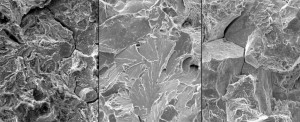
The fracture surfaces of the failed pin connections on C1, C2 and C3 were electrolytically cleaned to remove oxides, which mask the fracture signatures. The cleaned fracture surfaces were then observed through a SEM. The fracture examination on C1 and C2 revealed features typical of transgranular fracture. The examination also revealed signatures of intergranular cracking (Figure 7).
The presence of both intergranular and transgranular features indicates a mixed mode fracture morphology. As discussed, the presence of intergranular cracking is often considered proof of failure induced through environmentally assisted cracking, such as SSC or hydrogen embrittlement. However, a saver sub is unlikely to come into contact with downhole corrosive environment.
Moreover, review of the operating conditions and environment provided no evidence of a source of nascent hydrogen. In this instance, presence of a mixed mode of intergranular and transgranular morphology on the fracture surface, combined with the low CVN values, indicates that the failure is more likely associated with temper embrittlement of the material resulting from improper heat treatment of the component.
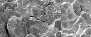
SEM analysis of C3 was also performed. However, no signatures were observed as the fracture surface was too corroded for examination.
To confirm if the subs underwent temper embrittlement, the fracture surface of the CVN impact test samples were analyzed under a SEM. Typically, examination of the fracture surface of CVN samples from a ductile material can present portions of ductile dimples and transgranular “cleavage” cracking.
This morphology is also expected on CVN samples that are machined from an inherently brittle material or a ductile material that has fractured through SSC or hydrogen embrittlement. The fracture examination of the CVN samples from the failed subs revealed mixed mode of intergranular, transgranular and some ductile dimple features (Figure 8).
This mixed mode of intergranular and transgranular cracking indicates that the subs likely underwent temper embrittlement resulting from improper heat treatment. Hence, presence of intergranular cracking does not confirm environmental cracking. Instead, CVN testing should be performed to check the fracture toughness of the material.
Additionally, the fracture surface of the CVN samples should be analyzed under a SEM to verify the fracture mode. Temper embrittlement of material is a strong possibility if the material presents low CVN values along with presence of intergranular or mixed mode of intergranular and transgranular cracking signatures on the fracture surface of the CVN sample.
Guidelines on Alloying Elements
Temper embrittlement is often associated with the concentration of certain trace alloying elements, such as arsenic, antimony, tin and especially phosphorus. These minor impurities segregate along the austenitic grain boundaries during the tempering process and cause cracking along the grain boundaries.
Molybdenum, tungsten and zirconium greatly reduce embrittlement, and nickel, titanium and vanadium slightly reduce the temper embrittlement effects.
API Specification 7-1 and Standard DS-1 do not have any requirements for chemistry on subs. However, API Specification 5DP and Standard DS-1 have chemistry requirements for drill pipe tube and tool joints for phosphorus (0.020% max) and sulfur (0.015% max).
The sulfur content obtained on all the three failures was above the maximum allowed for drill pipe tube. The phosphorus obtained on C3 was above the maximum requirement, while the content for C1 and C2 was near the maximum allowed. This provides basis for strict control on these elements to minimize the possibility of temper embrittlement problems.
If not already required in the governing standard, supplementary requirements on content of phosphorus (0.02% max) and sulfur (0.015% max) should be specified when tubular components are ordered.
Re-Heat Treatment
To check if the failure mechanism of the failed sub C1 was temper embrittlement, the sub material was re-heat treated. The re-heat treatment was also performed to confirm whether the sub was improperly heat-treated at the mill.
Sections of the failed pin connection were re-heat treated with the following conditions:
Condition 1: Temper at 657°C (1,215°F) for 45 min, and cool.
Condition 2: Austenitize at 872°C (1,602°F) for 55 min; water quench; temper at 1,215°F (657°C) for 45 min; and cool.
The heat treatment procedures listed in the material test report (MTR) were used for re-heat treatment of the sub material. These conditions were chosen because the tempering temperature listed in the MTR does not fall in the temper embrittlement range.
If the sub was heat-treated at the mill with the conditions indicated in the MTR, temper embrittlement likely would not have occurred. After re-heat treating the sections from the failed pin connection with the conditions listed above, CVN impact tests were performed.
Significant improvement in the CVN values was observed from the re-heat treated material under both conditions. The reason for higher CVN values obtained through Condition 1 compared with Condition 2 is that the Condition 1 material underwent a double tempering process at the mill, and again during the re-heat treatment process.
The minimum and average impact energy of the re-heat treated sections was greater than the minimum required value specified in API Specification 7-1 and Standard DS-1. This confirmed that the failed sub was not heat-treated to the parameters listed in the MTRs.
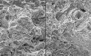
To check if temper embrittlement still existed, the fracture surfaces of the re-heat treated CVN samples were analyzed under a SEM. Figure 9 present the fracture surfaces of the re-heat treated CVN samples as seen under SEM.
Microvoid coalescence (seen as ductile dimples) was observed on the fracture surface of the CVN sample, which is indicative of ductile overload of the material. No features of intergranular or mixed mode of intergranular and transgranular cracking were observed.
Hence, temper embrittlement was eliminated by performing the re-heat treatment on the failed sub material. Temper embrittlement was eliminated with only tempering the sub material (Condition 1). This confirms that temper embrittlement can be reversed with a tempering process performed at the appropriate temperature.
Conclusions
1. Detection of intergranular cracking morphology on fracture surfaces of a failed component is often considered to be confirmation of failure through SSC or hydrogen embrittlement, even when no evidence exists for exposure to H2S or a source of nascent hydrogen.
Study of intergranular cracking related failures has shown that intergranular fractures can occur not only when the component is exposed to corrosive environment, such as aqueous H2S, but can also be caused by temper embrittlement of the material resulting from improper heat treatment.
2. Temper embrittlement typically occurs when carbon or low-alloy steels are held at or slowly cooled through the temperature range of 375°C (705°F) to 575°C (1,065°F) during the tempering process.
3. Temper embrittlement is often associated with the concentration of certain trace alloying elements, such as arsenic, antimony, tin and especially phosphorus. These minor impurities segregate along the austenitic grain boundaries during the tempering process and cause cracking along the grain boundaries. If not already required in the governing standard, supplementary requirements on content of phosphorus (0.02% max) and sulfur (0.015% max) should be specified when tubular components are ordered.
4. The fracture surface of a failed component that has experienced temper embrittlement can present intergranular or mixed mode of intergranular and transgranular fracture morphology when analyzed under a SEM.
5. Generally, temper embrittlement of a material, does not lead to a detectable drop in expected yield strength, tensile strength and percent elongation of the material. However, a drop in the CVN impact energy values is often experienced, and in cases of extreme embrittlement, there may be a drop in the percent reduction of area.
6. Since there is no major change in the tensile properties of the material, hardness testing cannot be used to detect temper embrittlement of a material. Performing CVN tests followed by examination of the fracture surface of the CVN sample under a SEM are necessary to ascertain failure through temper embrittlement.
7. If the fracture surface on the failed components presents signatures of intergranular fracture, then it should not be presumed that the failure is associated with environmental cracking like SSC. Instead, CVN testing should be performed to check if the material has low impact energy values.
Once tested, SEM analysis of the fracture surface of the CVN sample must be performed to check for intergranular or mixed mode of intergranular and transgranular cracking. Presence of intergranular or a mixed mode of intergranular and transgranular morphology on the fracture surface of the CVN samples, combined with low CVN values, indicates a failure more likely associated with temper embrittlement of the material.
8. If the component being tested, such as tubing, does not have sufficient thickness to machine minimum required size CVN samples according to the governing API specification (minimum size accepted by API is 10 mm x 5 mm), then CVN samples should be machined to 10 mm x 2.5 mm (¼-in.) size to perform CVN testing.
Although the values obtained through testing cannot be compared against API specification requirements, the fracture surface of the CVN samples can still be analyzed under a SEM to check for intergranular or mixed mode of intergranular and transgranular cracking.
9. Temper embrittlement is a reversible process. Carbon and low-alloy steels that have experienced temper embrittlement can be restored to their original (or expected) toughness by heating (tempering) to 600°C (1,100°F) or above, followed by rapid cooling to below approximately 300°C (570°F). Material susceptibility to temper embrittlement can also be reduced by strict control and reduction of embrittling impurities, such as phosphorus.
This article is based on SPE/IADC 139762, “Intergranular Cracking of Oil Field Tubular Components Resulting from the Tempering Process,” SPE/IADC Drilling Conference & Exhibition, Amsterdam, The Netherlands, 1-3 March 2011.
References
1. API Specification 7-1, Specification for Rotary drill Stem Elements, first edition, American Petroleum Institute (March 2006),
Section 7.5, Page 26.
2. API Specification 5DP, Specification for Drillpipe, first edition, American Petroleum Institute (August 2009), Table C.4, Page 86.
3. Hill, T.H.: Drill String Design and Failure Prevention, T H Hill Associates, Inc. (September 2002).
4. Metals handbook, Volume 4, Heat treating, ninth edition, American society for metals (November 1981), Page 84.
5. Metals handbook, Volume 11, Heat treating, ninth edition, American society for metals (November 1981), Page 6, 11, 99.
6. Metals handbook, Volume 12, Heat treating, ninth edition, American society for metals (November 1981), Page 13, 174.
7. Standard DS-1® Volume 1: Drilling Tubular Product Specification, third edition, fourth printing, T H Hill Associates, Inc. (January
2004), Table 3.2.1, Page 20 and Table 3.1, Page 13.
8. William T. Becker. ASM International Course 0335, Principles of Failure Analysis, Lesson 3: Ductile and Brittle Fracture, Page
61, 62, 63.

