NewsPeople, Companies and Products
Eni exercises third optional well on Ventura’s SSV Catarina
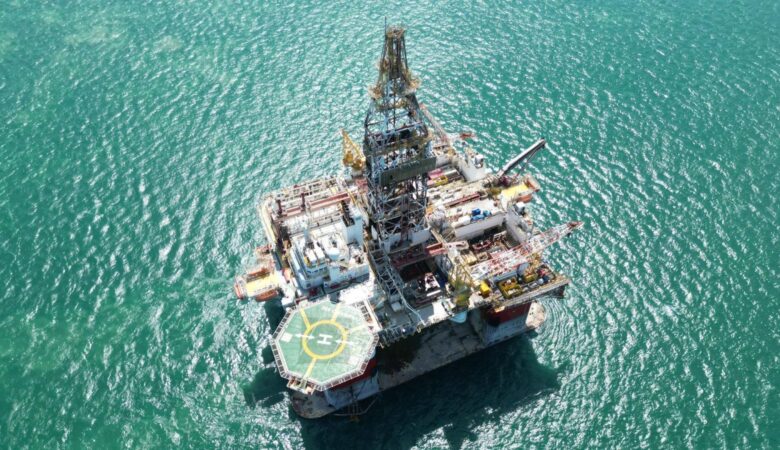
Eni Indonesia exercised the drilling and completion of the third of four optional wells in Indonesia for the Ventura Offshore semisubmersible drilling rig, SSV Catarina.
The exercise of this third optional well is expected to keep the rig utilized through Q2 2026 and further increases Ventura’s firm backlog by approximately $20 million. Further exercise by Eni of the remaining optional well in Indonesia could keep the rig utilized into Q3 2026.