Well control risks on HPHT wells may call for system upgrades
Enhanced kick detection, management systems and crew training may be required to maximize safety
By Ted Littlechild, EFC Group
High-pressure, high-temperature (HPHT) wells are defined differently throughout the industry. The UK Energy Institute’s Model Code of Safe Practice in the Petroleum Industry defines HPHT wells as “where undisturbed bottomhole temperature exceeds 300°F (149°C) and where mud weight in excess of 15.4 ppg is needed, or where pressure-control equipment over 10,000 psi is needed.”
The API does not yet specifically rule on HPHT wells and drilling, although changes in API specifications and recommended practices are anticipated.
It is possible to have HP without HT and HT without HP, often classed as “near-HPHT,” where wellhead pressures of 8,000 psi and 9,000 psi may be anticipated. These deserve as much attention as HPHT wells, especially where gas and condensation is expected.
Although much progress has been made in kick detection techniques in recent years, kicks still occur and vary in type, composition and severity. Kick detection is far from an exact science and, like many critical rig operations, can be subject to the vagaries of human decision-making and experience. As techniques for kick detection continue to improve, the global drive to drill deeper and to find hotter, higher-pressured reservoirs will push ahead as well.
If kicks are inevitable, what is therefore needed is a reliable kick control or kick management system, which must include the hardware and the trained personnel to minimize the significant risks.
Technology development timeline
The first ram-type BOP was developed in the early 1920s by James Abercrombie and Harry Cameron. First deployed in 1924, it was used to stop the routine gushing of successful wells.
Many other improvements in kick control/management followed, especially rotary drilling and improving mud technology to maintain control of pressurized reservoirs, as well as the development of hard-faced chokes and drilling manifolds to improve well control after a kick. These improvements helped, but they did not stop the kicks.
The industry’s operations kept moving forward, primarily offshore, with the added complications of placing BOPs subsea, having risers and the often remote locations of the rig. These issues helped to drive continual improvement of kick detection technology – more difficult on a heaving semi/drillship – as well as the development of kick control methods and crew training and experience.
Yet these developments didn’t stop kicks or blowouts. It is crucial that a rig is equipped with adequate systems to manage kicks to prevent them from developing into blowouts and to control them as quickly as possible, with minimal harm to the crew, the rig and the environment.
Two major North Sea blowouts in 1988 led to significant changes in UK legislation, as well as international practices.
All blowouts have different but equally significant consequences, and the September 1988 blowout in the Central Graben of the UK’s North Sea led to the establishment of an official definition of HPHT wells and to the development of HPHT codes and practices.
What we would now call HPHT wells have been drilled for decades. They were previously known as “difficult or hazardous wells,” which are accurate terms. The September 1988 incident resulted in the UK Department of Energy issuing a moratorium that stopped drilling on all wells requiring BOPs and manifolds rated beyond 10,000 psi and 300°F until specific well control equipment upgrades were installed on the rigs.
The main well control upgrades required by the UK Department of Energy in 1988 were the result of recognizing that HPHT wells introduced risks that had not necessarily been formally assessed and for which specific equipment and training were lacking. The UK government took steps to ensure that specific equipment to deal with the circumstances had to be installed and ready for operation. These included:
• High-temperature elastomeric seals in BOPs and wellheads;
• A properly engineered mud-gas separator in place of the poorboy degasser with a derrick vent line terminating at or above the crown and where flow rates, size and capacity were calculated;
• High-pressure overboard “blowdown” lines from the buffer tank, effectively bypassing the mud/gas separator: These 4-in./5-in. lines have the same pressure rating as the buffer (5 ksi or 10 ksi) and ideally run straight overboard to port and starboard;
• A system for monitoring and recording temperatures, particularly in subsea BOPs, as well as pressures and temperatures upstream and downstream of both hydraulic chokes; and
• A hydrate inhibitor system set up for the injection of antifreeze immediately upstream of all chokes.
Further, the content of well control training for HPHT was prescribed. During the next few years, a series of UK Continental Shelf (UKCS) notices were issued addressing topics such as the detailed design of the mud-gas separator and liquid seal.
The second significant UKCS blowout was Piper Alpha in 1988. This disaster had nothing to do with drilling, HPHT or otherwise, but the number of fatalities was significant.
The incident was followed by Lord Cullen’s Enquiry and Report, which made many recommendations that would go on to drive a radical shift in the responsibility framework in the early ’90s. Since then, operators and drilling contractors have been required to develop safety cases using risk analysis and matching equipment to risks.
One result is that operators and drilling contractors have developed their own HPHT operating procedures, and although many of these differ in detail, they are similar in their main conclusions and requirements.
Since the early ’90s, some or all of these equipment upgrades have been fitted to many 15,000 psi-rated rigs worldwide and to some 10,000 psi-rated units. They are not only suitable for HPHT operations but are sensible additions to well control systems for most rigs.
In some parts of the world, there has been little or nothing by way of HPHT operations, but as energy demand grows and the production of reservoirs plateaus and declines, it is inevitable that ever-deeper wells will be planned and drilled in all regions. The early name of “difficult” or “hazardous” wells is accurate, so the issue is how to mitigate the hazards when drilling deeper into these hotter, higher-pressure zones.
Upgrades
It should be assumed that the rig selected for an HPHT program is already equipped with, among other things:
• A 15,000-psi stack;
• At least one choke and one kill line with HCR valves;
• 15,000 psi-rated chokes – usually four chokes with a split buffer tank, because well kill operations can take days and weeks to complete. Normally, two chokes are hydraulic and two are manual, although that’s conventional and we occasionally have manifolds with four actuated chokes;
• An updated mud system, with plenty of capacity for solids control, mud mixing and bulk handling; and
• Properly functioning safety systems, e.g., gas detection, deluge systems, life boats, etc.
These assumptions cover the way in which a newbuild rig will often leave a yard: equipped with 15,000-psi equipment but not ready for HPHT operations. To be fully prepared for HPHT operations, the rig requires most if not all of the following additional systems, which are often added to newbuilds after leaving the yard.
Control & monitoring systems
• Liquid seal monitor;
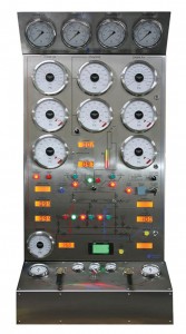
• Finescale pressure gauges – high-resolution manifold, analogue pressure gauges;
• Interlocked overboard valve control system;
• Open/close status indication of manual valves;
• Temperature up/downstream of both remote chokes;
• Glycol injection unit;
• Formation integrity test/leak-off test (FIT/LOT); and
• Possible future requirements, e.g. BOP event logger.
Liquid seal monitoring system
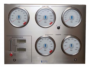
The liquid seal monitoring system reflects how the liquid seal operates on the basis of differential pressure across the seal. An alarm alerts the driller to imminent loss of his liquid seal and the need to take action.
Finescale pressure gauges
Large analogue gauges, which considerably improve the driller’s ability to see small pressure changes in the manifolds: choke & kill (C&K), standpipe (sometimes S/P 1 and 2) and sometimes cement/kill pump. Interface analogue gauges can be preferred to digital gauges because analogues have more visibility. Full-scale bourdon tube gauges showing drill pipe and casing pressures are an API requirement for choke control systems (API Specification 16C), so the finescale gauges augment them.
Interlocked overboard valve control system
At its simplest, this system controls and sequences two valves: the buffer tank to mud-gas separator line valve and the blowdown valve (the buffer to overboard line valve). These valves, usually 4-in./5-in. to match the lines, are hydraulic and rated to the same pressure as the buffer (5,000 psi or 10,000 psi OP) and are interlocked so that fluids do not become trapped in the buffer tank but can either flow through the mud-gas separator or overboard.
There are usually two overboard lines, so there may well be three or four hydraulic valves to be controlled and interlocked to ensure that well fluids are not trapped. An override switch is needed so that, when not operational, the buffer can be closed off and pressure tested.
Furthermore, the choke control system often generates hydraulic power for control of additional overboard valves. When this is the case, an additional accumulator should be added so that the open/close performance of the chokes is not affected and the API requirement to close the choke within 30 seconds (20 seconds with an accumulator) is maintained.
Open/close status indication of manual valves
The UK Energy Institute publication referred to earlier recommends that sufficient C&K manifold valves be remotely actuated to “avoid the close proximity of personnel to high-pressure lines.” The open/close position of these actuated valves must be directly monitored using proximity switches with their status displayed on a panel.
The manifold also has a quantity of manual valves. They do not usually have a rising stem, and their open/close status is not readily apparent. This means that the fluid flow path through the manifold is not immediately obvious, and mistakes can be made during well control incidents.
The solution is to monitor the status of the manual valves, and this can be done using sensors that monitor valve stem rotation; the signal is fed back to a screen or pairs of LEDs on a panel.
Temperature upstream & downstream of remote chokes
Temperature changes present two potential dangers: high temperatures upstream of the chokes and low temperatures downstream of the chokes.
The danger of high temperatures is that of exceeding the temperature rating of the ram, valve and choke seals and elastomers. If that happens, well flow can no longer be effectively choked back, and the well control capability of the rig becomes dangerously reduced.
The danger of low temperatures downstream of the chokes is that, as the chokes do their job and create a pressure drop, an associated temperature drop occurs, leading to the dangers of the gas component freezing into hydrates, restricting the flow and even blocking the low-pressure manifold pipe work. Again, the result will be that well flow can no longer be effectively controlled, and the well control capability of the rig becomes dangerously reduced.
Monitoring mud temperature
In a manifold, monitoring mud temperature should take place at locations where mud is flowing, not at a dead end such as an instrument block. Wrap-around sensors effectively work. They do not require additional drilling and tapping of the manifold, and they can be located, more or less, at the best positions for temperature monitoring.
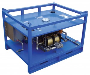
Glycol injection unit
To prevent hydrates from forming downstream of the chokes and blocking the manifold flow lines, glycol is injected as a hydrate inhibitor, or antifreeze, upstream of each choke.
A dedicated glycol injection unit is needed, with dual pumps that match/exceed manifold pressures so the pumps each need to be able to output more than one liter/min at 15,000 psi. The pumps are usually rated to a maximum of 23,000 psi.
One question often asked is, “How much glycol is needed?” The answer simply is, “Enough to do the job,” which is not very helpful, but well fluid and gas compositions and rates of flow in exploration wells are not usually known in advance, and experience has shown that “the one liter/min at 15,000 psi” rule of thumb works.
FIT/LOT
Formation integrity tests and leak-off tests are traditionally recorded using graph paper and pencil, and decisions are taken onboard.
Systems are available for monitoring the FIT/LOT testing, recording to a PC and transmitting the data to shore-based experts in real time, who can then help with the FIT limit decision-making. One further advantage is that FIT/LOT data are recorded electronically and can be used to help with future drilling operations and well planning.
Looking ahead
Managed pressure drilling (MPD) is a technique being adopted globally, especially in HPHT wells, providing a considerable improvement in well control and reduction the frequency of kicks. MPD allows greater control of bottomhole pressures while drilling, but it is important to realize that when a kick is detected, it is the rig’s BOP, C&K manifold and systems like the ones described in this article that are the used for kick control purposes.
As a result of the 2010 Macondo blowout, API and IADC committees and joint task groups have been working on well control issues and equipment. There are likely to be some far-reaching changes, especially – but not only – aimed at deepwater drilling and HPHT drilling. Full details of these changes are not yet known, but they are likely to focus on BOP configurations, BOP testing, BOP data handling and off-rig transfer, C&K manifolds, mud/gas separator issues, and personnel competence and training.
Greater procedural rigor and attention to detail is required. Through time, as shallow, “easy” oil and gas fields have been discovered, developed and depleted, operators have had to drill deeper into hotter, higher-pressured reservoirs. This global trend is gradually exposing more operators to HPHT conditions, with potential well control issues.
Thorough equipment upgrades and crew preparation are prerequisites to minimize the risks and to maximize safety, environmental protection and operational profitability.
This article is based on a presentation at the 2010 IADC Well Control Middle East Conference & Exhibition, 29-30 November in Manama, Bahrain.
EFC Group, formerly Electro-Flow Controls, provides well control systems for HPHT drilling focusing on enhancing the systems that are typically provided with the BOP, manifolds and accessories.


