New riser safety system enables effective contingency riser gas handling, MPD in deepwater
By Max Yeo, Alex Macgregor, Henry Pinkstone, Managed Pressure Operations
Deepwater drilling projects are inherently more challenging to execute due to the increased risks and complexity associated with narrow and unpredictable drilling formation pressure margins. With regards to well control, small gas influxes that are initially dissolved in the drilling mud can remain in solution and be circulated above the subsea BOP, undetected, before breaking out in the riser. This can result in an overboard diversion of oil-based fluids, or worst case unloading the riser through the rotary table.
In terms of drilling operations, the narrow and unpredictable nature of formation pressure margins in offshore operations often require solutions that can dynamically control wellbore pressures to complete a hole section safely and efficiently. Finally, the lack of ability to respond quickly to an influx can result in kick sizes that cause significant safety concerns, as well as NPT and higher drilling costs.
Managed Pressure Operations (MPO) has designed a new riser safety system (RSS) to allow the effective implementation of contingency riser gas handling (RGH) and managed pressure drilling (MPD) on deepwater operations. The RSS is intended to reduce the environmental risks associated with diverting an uncontrolled flow of gas and drilling fluid overboard with a conventional riser diverter system.
The RSS has the capability to rapidly increase MPD applied surface back pressure (ASBP) during a well control event to immediately take wells overbalanced and stop influxes prior to closing in the subsea BOP. The system includes both the subsea and surface equipment required to control pressure throughout the wellbore, and specifically within the riser, as well as safely manage high return flow rates.
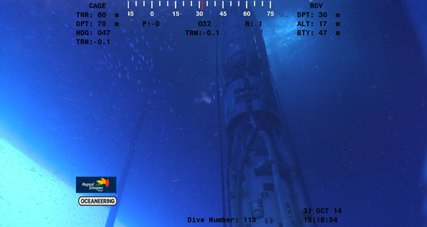
The RSS subsea equipment is also designed to reduce the operational risks and deployment time associated with manual moonpool installation operations. As such, the subsea equipment is designed to drift through the rotary table and be deployed in the same ways as a joint of riser. Once suspended in the rotary table by the spider slips, the remainder of the RSS deployment includes a control umbilical connection and return hose gooseneck connection of three 5.5-in. RSS mud return hoses. The RSS hose gooseneck latch connection system consists of an adjustable padeye system, hydraulic latching mechanism and clearance for a reasonable range of rotational offset during the hose connection process.
By deploying the RSS equipment subsea beneath the slip joint, the slip joint does not present the pressure limiter for the riser system, and the rig’s full operational heave capacity is maintained. Traditionally, the slip joint packers can hold only 250-500 psi. When the RSS annulars are closed, the riser system is capable of holding up to 3,000 psi of backpressure depending on the mud weight, seawater depth, riser class and rating of the lower marine riser package dependent on the global riser analysis.
The RSS deploys an active sealing system intended for MPD operations that forms a dual wellbore seal around the drill string. The RSS does not have any rotating components and is designed for use with 8.5-in. or larger drill pipe tool joint outer diameter. The RGH annular can be closed to 3,000 psi in 3 seconds on drill pipe or open hole in order to seal the riser and safely control riser gas break events, instead of diverting riser flow overboard, as well as rapidly apply ASBP during a well control event.
Below the riser drilling device (RDD) and RGH annular, the RSS flowspool consisting of dual 5.5-in. API 17K return hoses is used to flow high-rate returns to a pressure control manifold at surface. A third API 17K, 5.5-in. hose is used as a conduit for a riser overpressure relief protection system installed on the flowspool. This relief line may vent riser flow directly to the high flow-rate ultra mud-gas separator (UMGS) or directly overboard as with a traditional diverter system. The pressure relief system is designed to protect the riser from overpressure and be re-sealable following an overpressure event, hence preventing an unnecessary retrieval of the RSS equipment to surface.
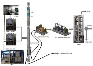
At the surface, the RSS includes a buffer manifold, pressure control manifold, high flow-rate UMGS and additional pressure relief protection systems. The buffer manifold provides tie-ins for seawater injection and riser booster pump to allow mud cap drilling operations, and glycol injection during RGH operations. The pressure control manifold is designed to control ASBP during MPD and RGH operations. The high flow rate UMGS is rated to peak flow rates of 4,000 gpm liquid and 80 MMscfd gas.
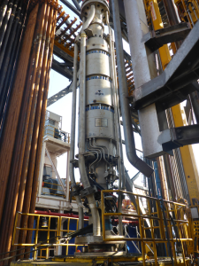
In summary, the RSS includes a subsea-deployable RSS flowspool, an RGH annular and an RDD. The dual RDD and riser RGH annular housing is designed as a single, combined triple annular assembly known as the riser safety device (RSD).
When deploying this RSS configuration, the RSS flowspool and the RSD assembly are run as two separate modules of riser. This is also in consideration of the rig riser skate load handling capacity, with each assembly designed to weigh less than 40 metric tons. These systems are deployed directly below the telescopic joint and above the last joint of marine riser. These systems are able to drift through a 49-in. rotary table on rigs where rigid, choke, kill and booster lines terminate on a termination joint or 60.5-in. rotary table for rigs where the peripheral lines terminate at the slip joint and are run over the RSS.
RSS flowspool
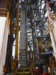
The RSS flowspool is the main assembly that contains the essential components for controlling all RDD/RGH functions. The main functions of the RSS flowspool are:
• To provide a flow outlet under the RDD or RGH annular to allow mud return flow from the well and riser to be diverted to the high flow rate gas-handling manifold at surface during normal RSS operation.
• To provide pressure relief to protect the riser from conditions of overpressure in the event of mud return line plugging or inadvertent closing of the RSS flowspool outlet isolation valves.
The RSS flowspool is built with universal connection compact end flanges adaptable by using separate crossovers to any type of riser connection. The RSS flowspool body is rated to 4.0 million lb load. The upper body is designed to accommodate installation of subsea accumulators for the RGH/RDD functions.
The RSS flowspool has three 5.5-in. bore outlets on the mud flow diverter for riser returns. Two of the 5.5-in. outlets are available to deliver high flow rate returns to a pressure control manifold on the rig. The third 5.5-in. outlet is reserved as a pressure relief line to divert drilling returns overboard to protect the riser against overpressure in the event of a system failure.
The mud flow diverter isolates the wellbore from the hose with dual 6-in. API 6A ball valves, and these are configured in series to give redundancy for their sealing function. The 6-in. gooseneck hose assemblies are mounted to the RSS flowspool outlets to provide a connection for high flow rate hoses. Ultimately, the RSS mud hoses provide a conduit to transport riser returns from the RSS subsea to a pressure control manifold and a high flow rate mud gas separator at surface.
Local pressure and temperature transmitters installed on the RSS flowspool are intended to measure the pressure and temperature below the RDD and RGH annulars. The pressure range of these sensors is 0 to 2,300 psi. The sensors are placed sufficiently far apart so that an estimate of drilling fluid density can also be derived from the difference in pressure.
RDD for MPD
The RDD of the RSD is an offshore-capable MPD wellbore sealing system that is intended to improve on older RCD designs that have been used on previous offshore drilling operations. The RDD differs in that it does not have a bearing assembly or other rotating components. Excessive environmental loading during offshore drilling operations can cause older-type RCD bearing assemblies to fail. Additionally, the RDD offers the capability to actively seal in the wellbore by compressing its seal sleeve with spherical packers. An active sealing system permits increasing the sealing pressure applied to the seal sleeve to maintain seal integrity even as the seal sleeves wear. Older RCDs traditionally have a passive sealing system, which results in a loss in wellbore sealing integrity as the drill string friction wears away the RCD seal element. The RDD seal sleeve can be installed and replaced by using a mechanical dedicated running and retrieval tool.
RDD seal sleeve
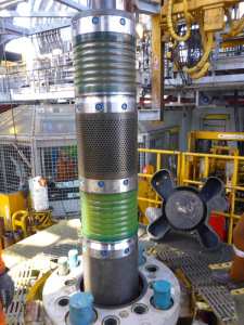
The consumable RDD seal wear sleeves are installed across the RDD annulars and closed on the drill string as the drill string is rotated to mitigate wear to the annular packers. Design and development of RDD seal sleeves and sealing elements was completed using finite element analysis (FEA) techniques, and the design verification was carried out with prototype and testing per API 16RCD.
Detailed lab-scale testing of elastomeric and polymeric materials was carried out to evaluate the mechanical properties of the materials and to specify these mathematical material model definitions in a non-linear FEA. These detailed material properties are required to capture the non-linear and nearly incompressible attributes of elastomeric materials in the simulations. Material properties for the elastomeric components were defined with strain energy potential functions to accurately capture the incompressible hyperelastic behavior of the material in the simulations.
Simulation results were used to evaluate the strength and life estimation of the sealing components and to extract the closing pressure versus wellbore pressure relationships. Correlation between the simulation results and the prototype test results increases the reliability of the simulation techniques used for further design improvements and other design variants. The seal sleeves and RDD system were then extensively tested, exceeding API 16RCD requirements to establish actual operational parameters, using the MPO test rig in Singapore.
Seal Integrity Circuit (SIC) system
The main design purpose of the RDD SIC is to provide a continuous supply of lubricating fluid across the RDD seal sleeve sealing surfaces. This controls and minimizes heat, friction coefficients and wear rates as a result of tubular rotation and reciprocation within the non-rotating seal sleeve over a large variance in wellbore pressures. SIC active drilling mud is injected between the two seal sleeves with the intention of lubricating upward between the upper seal sleeve and drilling string seal face, as well as downward through the lower seal sleeve and drill string seal face. When a tool joint passes through each seal sleeve, RDD annular piston pressure is controlled in order to permit the tool joint to pass with minimal wear to the seal sleeves and allow lubrication to continue. RDD annular piston pressure is increased following the passage through of a drill pipe tool joint.
When the non-rotating RDD seal sleeve assembly is pressed against the drill pipe during MPD operations, high friction between the contact surfaces may result in very high temperatures and wear that will shorten the life of the seal sleeve. The SIC injects active drilling mud into the perforated section between the upper and lower seals to reduce friction and heat generated during stripping and drilling operations, thereby increasing the life of the seal sleeve. This results in considerable rig-time cost savings and allows for extended operational life for the seal sleeves used with the RDD.
Operational parameters such as SIC injection pressure, volumes and cooling can be controlled from the surface control system. This is achieved by predetermined set points driven by manual inputs into the human machine interface. The programmable logic controller (PLC) interface that systematically monitors SIC injection and circulation pressures against wellbore or hydrostatic pressures. The PLC automatically adjusts the injection rate and pressure, circulating rate, and RDD annular packers closing pressure accordingly.
Gooseneck latch design
The hydraulically assisted RSS hose gooseneck latch assemblies are mounted to the outlets in the lower gallery of the RSS flowspool. The hose gooseneck latch assembly consists of a male pin, a hydraulic latching mechanism to secure the gooseneck, and isolation ball valves to isolate the riser from the RSS hoses when not in use. The hydraulic assist feature facilitates securing and removing gooseneck connections rapidly and remotely. The gooseneck has a female connection that mates directly with the male connection on the gooseneck latch assembly.
The RSS hose gooseneck design assists in handling the heavy 5 ½-in. ID RSS hoses necessary for MPD operations. This improves operator safety as the latching process does not require personnel to lock these hoses in near the latch point. The seals are all located on the male tube for ease of access when the equipment is on surface. On deployment, the hydraulic assistance controls the motion of lowering the gooseneck to the fully latched position.
To facilitate the hose gooseneck connection process, an adjustable padeye on the gooseneck is utilized to better ensure that the gooseneck is in a neutral stabbing position without being pitched forward or backward. On RSS hose retrieval, the hydraulic assistance overcomes the initial bonding frequently found in goosenecks caused by marine growth; this is much safer than using excessive tension on the moonpool tugger lines to remove the gooseneck.
This is an improvement over conventional well control hose gooseneck designs, which often mount the gooseneck attachment point on the riser tube, as this wears the seals resulting from differential movement as the riser system flexes. The gooseneck latch assembly design also permits up to 80° of rotation about the vertical axis to facilitate the hose makeup connection.
Lesson from first RSS deployment
Overall, the system deployed with minimal downtime.
• The RDD performed as designed.
• The first seal sleeve was run for 48 rotating hours with additional wear life left.
• The RDD seal sleeve deployed and latched as designed in 20 minutes.
• The hydraulically assisted RSS hose gooseneck latch assemblies performed as designed, taking 1 hour to deploy each RSS 6-in. hose.
• Flowspool isolation valves and pressure transducers all worked as designed.
• RGH annular performed as designed, closing and securing the riser in 3 seconds.
• SIC system proved that direct lubrication with active drilling mud injection allows easy operation and control, with no interruption or interference with the rigs active pit system or mass balance control.
The RSS subsea control multiplex (MUX) POD experienced reliability issues, mainly due to the limitations of current MUX POD subsea BOP power fluid pressure control regulator technology. The following upgrades are being implemented:
• New subsea BOP power fluid filtration unit is being installed to mitigate fluid contamination issues;
• Conversion of MUX to closed-loop system, with power fluid discharge to surface filtration tank system; and
• Converting RDD annulars to direct hydraulic control from surface using new umbilical and larger power fluid pressure control regulators housed in a regulator manifold, controlling RDD annular closing pressure from surface.
Conclusion
The RSS exhibits a technological innovation for well control, contingency RGH and MPD operations. The capability of the RGH system to seal in the riser and safely divert flow to a pressure control manifold and high flow rate UMGS within 3 seconds has set a new benchmark for MODU deepwater drilling operations. The RDD sealing mechanism contains dual API 16A annular housings and is tested to API 16 RCD.
By eliminating rotating components and designing an RDD seal sleeve that can accommodate the full range of drill pipe tool joint sizes while drifting through a 49-in. rotary table, the RDD is uniquely designed for offshore deepwater MPD operations. For adaption to any existing or new MODU, the RSS can be configured to adapt to any riser and control system. Not to be the limiting factor, the RSS subsea equipment is designed to meet or exceed the functional capacity and load rating of any riser system. Enhancements are ongoing for the RSS subsea equipment to further improve its cost and performance.
This article is based on a presentation at the 2015 IADC/SPE Managed Pressure Drilling & Underbalanced Operations Conference & Exhibition, 13-14 April, Dubai.


