Transocean’s Roddie Mackenzie aims to keep focus on advocacy, sustainability as IADC Chairman
Encouraging member participation, promoting importance of drilling and development of next-gen workforce at top of 2026 agenda
EVP and Chief Commercial Officer, Transocean
By Stephen Whitfield, Senior Editor
If there’s one word that would best sum up the career, so far, of Roddie Mackenzie, 2026 IADC Chairman and Transocean’s EVP and Chief Commercial Officer, it’s “yes.”
Mr Mackenzie’s journey through the oil and gas industry has been defined by a willingness to do anything and go anywhere in order to learn something new. It started in his college years, at the University of Strathclyde in Glasgow, Scotland, in the mid-1990s.
He was studying civil engineering with environmental studies, and up to that point oil and gas didn’t seem like an obvious career path. In fact, heading into his final year at university, he was mulling an offer to work for his uncle’s tunneling company, having previously completed an internship there to work on the Jubilee Line Extension as part of the London Underground.
But then he went to a career fair in that final year of university and met with a representative from Sedco Forex, which was then part of Schlumberger, now SLB. Following her suggestion, Mr Mackenzie applied for a development program, which led him to an interview with the company in the South of France.
He didn’t know exactly what the interview would entail. He didn’t know what job would come at the end of the program. He would just show up to the airport and have a ticket waiting for him.
After some encouragement from one of his professors, he said “yes.”
That “yes” led to three days of interviews alongside 14 other students from 12 countries.
At the end of the process, he was offered a spot in the company’s Technical Development Program. That led him to a training rig in France, then various other rigs in Algeria, Nigeria, Cameroon, Angola, Brazil and the US Gulf. He worked on all manner of rigs: land rigs, swamp barges, jackups, semisubmersibles and drillships in various operational and engineering roles – basically, doing whatever job the company had for him, even driving forklifts.
“There’s no other way around it,” Mr Mackenzie said of his early years in the industry. “Whenever anyone asks me for career advice, I tell them to always say ‘yes.’ It doesn’t matter what you’re being offered, wherever the posting happens to be, or what kind of job you have to do. Just say ‘yes.’ If you qualify the answer – I can’t move here, I can’t do this or that – then you’re always going to have that doubt in your mind because you said ‘no.’ Just go do it and see what happens.”
Following the merger of Sedco Forex and Transocean in 1999, Mr Mackenzie moved into project management, then into auditing as he made his way into shore-based roles. He held a variety of senior marketing roles before moving into the executive sphere, becoming Executive VP and Chief Commercial Officer at Transocean in 2022.
As he begins his term as IADC Chair this year, Mr Mackenzie sees advocacy as critical to the industry maintaining its social license to operate. That doesn’t just mean touting the work the industry’s doing with technology or emissions, but rather touting this industry as a great place for the next generation of workers to build their careers.
“I’m passionate about advocacy. Advocacy can be external facing, but I think it’s also important internally. You should be proud of where you work, who you work for and the work you’re engaged in. The safe and efficient delivery of energy and hydrocarbons to the world is a pretty big deal. I think that’s an important message that we have to get across,” Mr Mackenzie said.
Part of that advocacy involves senior leadership taking an active role in the development of students looking to make their way into the industry. For instance, Mr Mackenzie fully supports Transocean’s internship program and frequently talks to the IADC Young Professionals Committee about their career goals and progression. It’s important for industry leaders to instill a solid understanding of what this industry does, he noted, and how important it is to a functioning and prosperous society.
IADC’s work with its Student Chapters and Young Professionals Committee will continue to be a vital cog in the industry’s advocacy efforts. Beyond that, Mr Mackenzie pointed to the importance of IADC conferences and local chapters in building connections that can help young people make their way through the industry. As Chairman this year, Mr Mackenzie said he hopes to see more member participation in IADC functions.
“There’s always an ebb and flow to where we are in the market cycles and how much participation we get from the membership during those cycles,” Mr Mackenzie said. “But, in any instance, the more participation we have, the better the product IADC can give its membership and the industry at large. One of the things I really want to push is greater engagement with all the committees, all of the chapters and everyone going to the conferences. It’s going to be really important in helping us get our message across.”
Developing a sustainable business
Building the next generation of oilfield workers ties into another theme Mr Mackenzie aims to promote during his term as IADC Chairman: sustainability. It is paramount to drilling contractors maintaining their social license to operate, he said, and it’s vital for companies to tout the work they’ve done in this area.
But sustainability means more than just lowering emissions; companies also have to ensure their businesses are sustainable from a financial perspective. Mr Mackenzie comes into his chairman position at a time when both the onshore and offshore markets find themselves in a bit of a waiting game. Rig counts are not expected to see significant increases from 2025 levels. WTI and Brent Crude prices have been on a continual downward trend since the beginning of 2025 that is unlikely to reverse in the immediate future. Maintaining capital discipline and building resilient business models capable of withstanding flat or down markets is key.
As he puts it, drilling contractors can have all the aspirations in the world to lower emissions and contribute to a better environment, but if their business is unsustainable, “all of those things are really just lip service.”
“Regardless of the sector – whether you’re onshore or offshore – necessity dictates capital discipline. There just aren’t enough resources going around to be undisciplined. To me, that’s part of what our industry’s sustainability initiatives should be. That should always be a part of your strategy, because we just don’t have the luxury to not do that. We’re not in that moment in time where we can just significantly overbuild.”
Mr Mackenzie said he wants to see IADC continue to emphasize the importance of maintaining sustainable businesses: “That’s one of the things I want to see us stress from an IADC point of view. If we’re going to invest in training people, if we’re going to invest in employees, maintain technologies that make us safer and more efficient, our businesses have to be sustainable to support those efforts.”
Sustainability also means selective investments in technologies that can help unlock new efficiencies and keep rig crews safe, which have been a priority at Transocean in recent years.
For example, the company’s HaloGuard system, launched in 2021, became the drilling industry’s first safety system to integrate a wearable locating device with drill floor equipment and machine stoppage controls.
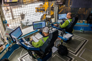
The company’s Operations Procedure System (OPS), deployed in 2023, digitizes procedures, workflows and dynamic processes to help guide the crews and minimize human error on the rig.
“We have gone to a digital platform on all of our procedures and reporting,” he said. “That really helps us analyze performance and trends, understand where our improvement areas are, and be much more deliberate in the areas that we decide to tackle so we can get the biggest bang for our buck in terms of deploying resources.”
The efficiencies realized through systems like the OPS can help make the rig safer, he said: “An efficient rig is a safe rig. We feel that if you’re procedurally disciplined and you’re using digitization to refine and enhance your procedures, you will be safer and you will be more efficient.”
Part of Mr Mackenzie’s job as Chief Commercial Officer involves pairing Transocean’s customers with the right technologies that can create demonstrable value for them. As such, he noted the importance for the industry to balance the trend of capital discipline with an appropriate emphasis on technology and R&D.
“At the end of the day, we’re in service to our customers,” he said. “However, digital transformation and efficiency initiatives require capital investment. It’s not realistic for drillers to have a large R&D budget, so we too have to be diligent, and we have to work carefully with our partners to find the right applications for testing and implementing technologies. If it doesn’t bring value to the end users, whether that be rig crews or customer well performance, then it doesn’t really have a business case.” DC