As drilling automation advances, building in cybersecurity resilience must remain core consideration
Companies must look at cross-layer monitoring of rig automation systems, tie cybersecurity monitoring to overall situational awareness of the rig
By Siv Hilde Houmb, Houmbinvest AS, and Fionn Iversen, Norwegian Research Centre
Integration of industrial control systems (ICS), or operational technology (OT) systems, and information technology (IT) systems has enabled use of real-time data for drilling process control and management. As a result, previously isolated OT sub-systems, such as the drilling control sub-systems, have become susceptible to cyber-attacks, thereby requiring protection.
Standard methods for protecting IT systems are not necessarily applicable to OT systems. Regular updating required for antivirus and malware applications is not suitable for continuous process control, and legacy OT systems have unsupported software and hardware, incompatible with new antivirus and malware applications. For the same reasons, standard patching or updating of operating systems (OS) is not straightforward for OT systems. Networking solutions have limitations in that these can detect viruses and other intrusions only at the communication layer. Tailoring of OT cybersecurity safeguards is therefore needed, and these must be compatible with the real-time requirements of OT systems, as well as protecting personnel, process and the environment.
The rig OT cybersecurity model should be aligned with the National Institute of Standards and Technology Cybersecurity Framework, defining cybersecurity in terms of functions: identify (risk), protect (safeguard), detect (attack), respond (to breach) and recover (system and operator procedures).
Further, a defense-in-depth and layered strategy, also known as zero trust model, has previously been recommended. Such a model is the basis for ISA/IEC 62443, the only internationally recognized cybersecurity standard for industrial automation and control systems (IACS).
With this basis, a key question becomes how to build a balanced and consistent cybersecurity resilience approach, while accounting for the capability and requirements of the modern rig OT system.
The Drilling OT System
Drilling operations on a modern drilling rig are widely varied. They span from manual operations, such as slips handling and doping of pipe, to mechanized control, e.g. Iron Roughneck, to programmable operational sequences, such as automated drill pipe reciprocation in the well, and automated optimized sequences, such as optimized automated pump startup. Industrial robots have been introduced to the rig, and there are ongoing efforts to robotize all machinery, thereby taking a large step toward autonomous operations.
However, most rigs have legacy component systems that must be accounted for when considering cyber defense.
Information and communications technology systems on drilling rigs have traditionally been fully segregated, with isolated control systems on separate supervisory control and data acquisition (SCADA) networks. These include:
• The drilling control system, consisting of machinery (mud pumps, top drive and drawworks);
• Sensors (hookload, pump pressure);
• Control units (programmable logic controllers); and
• Servers with software and hardware providing human-machine interfaces (HMIs) on one isolated network.
Such control systems were and still are proprietary, but without communication with other networks. All input for operations was provided by the control system operator – the driller, in the case of the drilling control system, including any configuration parameters required for e.g. PLC control algorithms.
Other system configuration or maintenance required physical connection, which was secured through locking mechanisms. Control system integrity is a very high priority, regardless of potential threat, as control system vendors are responsible for system reliability. With a completely isolated system, risk of external influence impacting system behavior was avoided, and the vendor had full control of the status of the system at all times. The modern drilling rig challenges this isolation and control regime.
Development in sensors and data communication systems, on the rig and downhole, has provided increasing amounts of data, with respect to both measurements sources and rates. This data enables process optimization through data analytics and modelling.
Depending on storage and computing requirements, real-time process data analytics and modeling may be performed, either in control system components or on more powerful integrated servers connected to the OT system, also known as edge computing. Such services may be provided by third parties, where the calculations can require input from multiple data acquisition systems on several of the rig control systems, including the drilling fluid processing system.
Edge models should ideally run autonomously. However, some level of configuration and maintenance of the models is normally required, necessitating access to an enterprise connection.
Anti-collision is an important part of automation, ensuring that the mechanized, remote-controlled or automated machinery cannot collide and cause damage or critical operational situations. Key to such anti-collision is that the equipment in question is controlled through the same network, or at least can communicate their position with low enough latency to achieve robust anti-collision. This can become a challenge for machinery/robots with control systems provided by different vendors as system openness can conflict with ensuring system integrity.
Until a rig is fully autonomous, some level of manual control is needed. Already at the electrified mechanized level, this involves remote control of machinery through a connected electronic control device. Today, the industrial network allows for control from a central control station – the drilling cabin. With modern communication network technology, it is in practice possible to control operations from a remote location, through connections such as VPN or VLAN. This represents a potential path for unauthorized access to rig OT systems and needs to be safeguarded.
Finally, the evolving robotics and control technology on the rig enables higher and higher levels of process automation, resulting in increased systems integration. This level of automation enables different control systems to integrate and coordinate, such as drilling control and pipe-handling systems for automated optimized pipe connections during drilling. Such integration needs to be properly safeguarded to protect the systems from each other and from potential unauthorized access, as well as to ensure system integrity.
Cybersecurity Requirements for Drilling Control System Automation
ICS should be built such that potential consequences of a cyber-attack are minimized with respect to personnel, equipment, wellbore and environment. It should be noted that, in engineering automation systems, some level of safeguarding is already in place.
Constraints are applied with respect to material (drill string) and environment (wellbore) limitations, and automatic detection of parameter discrepancy is applied combined with safe mode activation. As long as such safeguards are not compromised, they would also help to prevent unwanted behavior resulting from cybersecurity breaches.
Indeed, the idea of detection of discrepancies or inconsistent system behavior may be developed further for strengthening safeguarding against cyber-attacks, both for legacy and automation rig systems.
Automation principles
Existing drilling control systems are built for control through HMIs. Critical safety issues for systems control are:
1. Anti-collision, i.e., avoidance of collision of machinery on the rig; and
2. Avoidance of too high loads on machinery and equipment, with risk of failure.
Safety mechanisms are built into drilling control systems to ensure this. It is then the driller’s responsibility to protect the integrity of the wellbore and to react when wellbore integrity is breached, e.g. if a kick is experienced.
With drilling automation development, the system needs to take over some of this responsibility, as the system now automatically chooses operational parameters, such as rotational velocity of drill string, tripping speed, pump rate, etc. With drilling systems automation, the drilling control system must therefore also:
3. Protect the well from failure.
Principles for drilling systems automation as described by de Wardt et al. shall ensure this. Key elements to such protection are:
3a. Limit operational parameters to within available window (similar to “envelope protection” from aviation) of well integrity – process safeguards;
3b. Automatic detection and response to critical process conditions, such as stuck pipe – process safety triggers
The available operational window of the well is not always known, particularly for exploration wells. However, estimates may be automatically calculated during operations, based on existing information, and fed to the control system for automatic constraints (3a). Such constraints may be applied on the PLC level.
Automatic detection of critical process conditions can be made through comparison with expected behavior, derived either through simple trending or through more advanced predictive modeling. Such detection is, however, challenging, as comparison with predictions is not normally possible in the PLCs and needs to be done on a higher level, with subsequent critical requirements for latency and time synchronization. This requires protocols suitable for such requirements.
With the set of safety measures as described in place, automated procedures and sequences may be applied. Automated sequences may be implemented using existing PLC algorithms, with setpoint parameters from higher level optimization calculations on the “edge.”
What can go wrong?
What can go wrong – i.e., where can a cyber-attack influence the operational control, and what can the consequences be?
The most critical cyber-attacks would be those that affect well barriers. If instruments are compromised that affect measurement or mixing of the drilling fluid, or monitoring of outer casing pressures, then control of barriers may be lost. For optimized automated tripping control, cyber-attacks influencing the speed of tripping can cause both kicks and losses.
Further, the setpoint control, i.e. ensuring that the machine behavior is as specified by the setpoints, is critical for ensuring safe operation of equipment and requires an additional layer of PLC algorithms. It is critical that such algorithms function properly, in addition to having correct setpoints. A cyber-attack could cause a mismatch and damage equipment and personnel. It is, therefore, essential with effective barriers and cyber-attack detection and response, as well as continuously evaluation of the cyber risks, as discussed in the example below.
Automation Example: Tripping Automation with Safeguards
Tripping operations can be optimized within the constraints of the operational pressure window, where a hydraulics model is used for estimating downhole pressure in the optimization process, constrained by either fracture pressure or pore pressure, depending on the direction of pipe movement.
For these calculations, the hydraulics model can be run on the drilling control system server, a specific automation calculation server, or through an edge service. The model may also be run on a powerful PLC or single-board computer (SBC), if sufficiently simplified. For good optimization, the hydraulics model requires transient capability, as the acceleration and deceleration of the drill pipe when tripping has a significant impact on the resulting pressure variation.
There are additional needs for situational awareness and cybersecurity monitoring as computations and decision making are made on lower layers, as well as across layers, and to ensure correctness of the involved data and components.
The following minimal input must be provided for optimization: geopressure profiles, well and drill string geometry, bit depth, and drilling fluid properties, including density and rheology. Ideally, the drilling control system can supply drill string geometry input from the manually entered electronic tally together with real-time bit depth, calculated using drilling control system algorithms.
Drilling fluid properties, such as density and rheology, may also be electronically available in real time from the drilling fluids processing system. The well and casing geometry is, however, normally not available electronically, so manual input must be provided, either through the drilling control system HMI or a proprietary automation server HMI.
The operational setpoints resulting from the optimization are subsequently communicated as input to the drilling control system and then communicated further to a specific automation PLC containing the automated control algorithms, from which setpoints are continuously communicated to the machinery PLC (drawworks), or directly to the drawworks PLC with implemented automated control algorithm. Special automation PLCs can be used, adding an additional layer to the machine control.
Subsequently optimized automation of tripping may be performed either automatically or with operational envelopes applied as constraints to driller-activated control signals from the system HMI. Application of control algorithms on the control (PLC) level give the quickest response times, and help ensure that any delays or errors in calculations do not influence the automation sequence, as it is communicated as a whole.
Automatic interrupt functionality can help to ensure safe automated tripping operations in the case of unexpected downhole response, such as excessive force on the drill string caused by wellbore irregularities or cuttings beds, potentially resulting in packoff and/or damage to the drill string. Algorithms for such safety mechanisms need to be on the same control level as the automated sequences or envelope protection and be given higher priority.
As such, an algorithm must act on the deviation from expected forces, it requires at least a drill string mechanics model taking as input material parameters (linear weight), wellbore geometry, drill string geometry and bit depth. Linear weight is ideally available from the electronic tally, stored in the drilling control system database, but may need to be entered manually through automation system HMI. Calculations of expected loads as a function of drill string rate of movement may be performed either on rig system servers or through an edge service, and subsequently communicated to the relevant PLC.
Securing Drilling Automation Systems
A commonly used reference model for IACS is the Purdue reference architecture. The Purdue model is the basis for ISA/IEC 62443, the industry standard for securing IACS and a core component of ISA95.
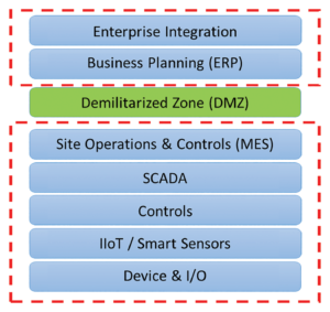
As illustrated in Figure 2, the Purdue model partitions the network into various zones, where the enterprise side is separated from the automation and control side by means of a demilitarized zone (DMZ), also known as a data transmission zone. The communication in and out of the DMZ is usually controlled by at least two firewalls – one facing the enterprise zone and one facing the automation and control zone.
Further, each firewall has a carefully configured access control list that protects the automation and control zone and its systems. This is usually referred to as perimeter defense. Additionally, encryption, authentication and auditing of communication within the automation and control systems are achieved using OPC-UA.
The IADC Guidelines for Baseline Cybersecurity for Drilling Assets defines a baseline set of cybersecurity functions for rig OT systems. This involves security awareness, security processes, risk management, secure remote connection, perimeter defense, network segmentation, hardening, malware protection, monitoring, authentication, access control and auditing (logging).
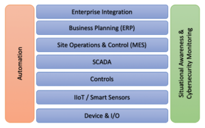
The assumption behind this cybersecurity strategy is a controlled and secure separation between the rig OT systems, as well as between the rig IT network and the rig OT systems. This assumption is broken as soon as equipment on lower layers (e.g., PLCs) communicates directly with equipment on higher layers (e.g., computation services/servers), such as might be the case with drilling automation systems or in cases where advanced computation and decision control are performed within one layer (e.g., edge computing). In such cases, the firewalls of the DMZ are not involved in the communication, and there is no visibility into the communication.
Consequently, the actual cybersecurity protection depends on the way the drilling automation systems are built and deployed. Therefore, crucial questions involved in determining the actual cybersecurity protection and needs are:
• How is the layered model deployed?
• How are the automation controls built into the drilling control system?
• How is data communicated?
• What are the protection mechanisms built into the automation controls?
• Have additional hardware or software components been added to the lower layers?
• What cybersecurity measures have been added into each component in the drilling automation system?
• How it can be determined whether any of the automation components have been compromised?
For the example of tripping automation with safeguards, it involves a hydraulics model used for estimating downhole pressure that could be run in multiple manners, such as on the drilling control system server on a specific automation calculation server, through an edge service, on a powerful PLC or on an SBC, depending on the specific implementation.
Further, there is a set of data involved in the calculations where most of these data points, except for the well and casing geometry, could be made available electronically. Other data points would need to be provided manually, such as through the drilling control system HMI or an automation server HMI of some sort. The result from the calculation is then communicated as input to the drilling control system, and further to automation PLCs containing the automation algorithms, from which setpoints are continuously communicated to the machinery PLC (drawworks), or directly to the drawworks PLC with implemented automated control algorithms.
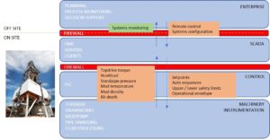
This example involves communication across layers (Figure 3) and requires protection of the actual components themselves (server, edge services, PLC, SBC, HMI and algorithms) and the data communication, as well as the data itself. Also, the example includes real-time requirements in terms of delivery of data and depends on the availability and integrity of the involved hardware, software, algorithms and data.
The IADC Guidelines for Baseline Cybersecurity for Drilling Assets does not address the cybersecurity challenges of cross-layer drilling automation systems, as it does not explicitly cover protection of lower-level devices such as PLCs and SBC, nor does it define how to protect edge services and drilling automation data. The guidelines defines the need for network segmentation, malware protection, monitoring and hardening, which can be applied to the drilling automation network and systems.
However, there are additional needs for situational awareness and cybersecurity monitoring as computations and decision making are made on lower layers, as well as across layers, and to ensure correctness of the involved data and components. This additional monitoring is essential for detecting discrepancies in data, software, hardware and algorithms involved in the automation sequence, and to determine the cause of the discrepancy.
Situational Awareness and Cybersecurity Monitoring
Drilling automation systems already have built-in safeguards to help ensure safe operations such as automated tripping, as discussed. Various safety parameters are monitored to help detect discrepancies that could affect the safety safeguards and eventually lead to unexpected downhole response.
As cyber-attacks could affect these safeguards, it is important to add cybersecurity to the list of potential causes for discrepancies in safety parameters and safety safeguards, and to use these to aid in detecting cyber-related incidents. However, as some cyber-attacks operate on the inside of PLCs and HMIs, it is also necessary to augment such equipment with specific cybersecurity monitoring.
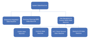
Cybersecurity monitoring should be on both the control networks and the devices/hosts (PLCs, HMIs, SBCs, engineering workstations, servers, historians, etc), and cover all layers of the drilling automation system (Figure 4). It’s important to obtain a sufficiently detailed situational awareness of each device/host on each layer and to aggregate the host information with situational awareness details from the networks within each layer of the system.
This information then needs to be structured and combined to derive the system cybersecurity status, which should be based on all available observations, including safety parameters, drilling process parameters, maintenance plans, software management, cybersecurity monitoring, situational awareness parameters, and similar.
Detecting discrepancies or inconsistent system behavior and attributing the observation, such as determining that it is caused by a cyber-attack, is essential to ensure safe operations of a drilling automation system. There will be, as discussed, various monitoring parameters and approaches for each layer that are combined into a holistic situational awareness view, aggregated over the various system layers. This is achieved through a hierarchical state machine model (Figure 4). Each state machine has several inputs and is composed of a distinct set of capabilities to model the “local” situational awareness. Examples include:
• Device & I/O: status monitoring of sensor data, device and I/O state, etc;
• IIoT/smart sensors: machine learning and parameter monitoring;
• Controls: machine learning, memory block monitoring (deep monitoring) and parameter monitoring;
• SCADA: machine learning, safety and process parameter monitoring;
• MES: machine learning, safety and process parameter monitoring;
• ERP: antivirus, IDS/IPS, business process monitoring; and
• Enterprise integration: antivirus, IDS/IPS, business process monitoring.
Summary and Conclusions
The need for real-time data and the rate of automation have led to a tighter integration of OT systems with the enterprise or IT systems on a rig. As a result, cybersecurity has become more important, necessitating built-in cyber resilience of rig OT systems. This is especially important for drilling automation systems.
The IADC Guidelines for Baseline Cybersecurity for Drilling Assets provides a foundation for building cyber resilience into drilling systems. However, the guidelines do not address the need for cross-layer monitoring of rig automation systems, nor does it tie cybersecurity monitoring to the overall situational awareness of the rig and the well, as one of many cases of safety or operational-related discrepancies.
Such a monitoring system needs to monitor various parameters, both on the control networks and on the PLCs, HMIs, servers and other hosts in the drilling automation system, as well as aggregating the cyber-related data with safety-related and operational data to determine the cause of discrepancies.
Such an approach would also be in alignment with current drilling automation development, where process discrepancy detection and automated mediating action based on situational awareness is a key ingredient. This systemwide situational awareness will enable a better understanding of what the potential impacts of cyber-attacks could be and consequently what the best mitigating actions would be. DC

