Light annular mud cap drilling, downhole isolation valve help to drill fractured gas reservoir in Indonesia
Case study from South Sumatra Basin shows technology deployment allowed drilling to continue through total loss circulation in massively fractured reservoir
By Enos Eben Ezer and Andi Pratama, SKK Migas; Fikri Irawan, Weatherford

An operator in Indonesia sought to drill on a gas field that lies on the western flank of the Central Palembang Sub-basin, in the South Sumatra Basin. South Sumatra is a Tertiary back-arc basin, approximately 500 km by 300 km. The pre-Tertiary rocks provide the lower reservoir portion of the gas field, while the upper portion of the reservoir is within porous Tertiary sediments of the Lower Talang Akar and Batu Raja formations. The Tertiary and pre-Tertiary reservoir rocks are enhanced by natural fractures.
Drilling results from three previous wells, which are still producing at significant gas rates, indicated that significant fractures were encountered in the Batu Raja formation and in the Pre-Tertiary. For a single Pre-Tertiary Basement test, the bottomhole absolute open flow (AOF) was 237 million standard cu ft/day. For the commingled Pre-Tertiary Basement and Batu Raja formation test, the bottomhole AOF was 1,097 million standard cu ft/day.
This article focuses on the utilization of light annular mud cap drilling (LAMCD) and a downhole isolation valve (DIV) system during the drilling of a well (Well X) on this field. The field’s geological information will be discussed, and a summary of the drilling program will be provided.
Drilling challenges
Unlike the Central Sumatra province, drilling operations in the Southern Sumatra fields often encounter problems that lead to nonproductive time. Common problems include:
• Tight hole/sloughing/swelling shale/mud ring: These issues may occur due to improper mud weights and/or insufficient chemical inhibition, particularly in the shale-predominant section, which are the Lower Palembang and the Telisa Shale zone.
• Formation overpressure: The formation pressure prediction for Well X was based on adjacent development wells that had been drilled previously.
• High temperatures and H2S and CO2 contamination: Bottomhole static temperatures (BHST) at total depth are above 300°F, with CO2 around 6% and 10 ppm H2S.
• Hard drilling, gas kick and lost circulation: Hard drilling in the extensive fractured formation is a common problem in this area. The nature of the fractured formation leads to severe lost-circulation problems. At the same time, potential gas flow may occur while drilling in the Baturaja Carbonate and the Pre-Tertiary, which is granite at this location.
Mud requirement and LAMCD

Three types of drilling fluids were utilized to drill Well X, starting with water-based mud for the surface section. Synthetic-based mud (SBM) was selected for the intermediate section to minimize the risk of hole stability due to overpressure zones in the Telisa formation and potential swelling effects. For the production section, fresh water (sacrificial) was selected for its lower costs, easier handling and availability.
To maintain the integrity of the annulus while drilling in a lost-circulation zone, light annular mud (LAM) was required. The LAM weight was designed to be lower than the fractured zone pressure gradient to avoid further lost circulation. Drilling commenced with no fluid returns to surface, where an annulus fluid column, assisted by surface pressure, was maintained above a formation capable of accepting fluid and cuttings. The LAM would transport all cuttings into the fracture. Any gas migration in the annulus would be countered by bullheading from surface.
DIV design and installation
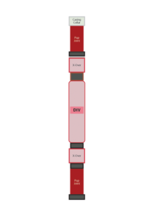
The DIV was run as an integral part of the casing program, allowing full-bore passage for the drilling and completion bottomhole assemblies (BHAs). The system is actuated by a dual encapsulated control line that is run external to the casing and activated by a surface control unit.
The DIV acts as downhole barrier that utilizes a flapper-type seal mechanism to prevent pressure at surface. The flapper is operated to the open position when the BHA or completion string passes through and is closed when nothing is in the well.
Tripping in or out of a live well requires special procedures in consideration of the additional forces acting on the pipe. A procedure was put in place to prevent the drill pipe from being pushed out of the well.
Well construction
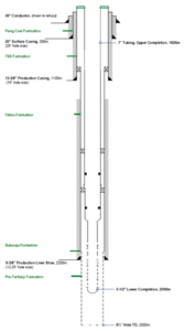
The DIV was installed in retrievable mode as part of the tieback string. The 9 5/8-in. casing was run prior to the tieback installation. Casing installation proceeded as normal until the DIV was ready to be picked up.
After running the control line through the sheave and connecting it to the body, the DIV flapper was function-tested and pressure-tested. The DIV control line pressure was maintained at 500 psi at the open side and 200 psi at the closed side by means of the surface control unit as an indication of control line leakage. DIV control line clamps were installed at every casing collar from the first joint until surface.
Production hole section
Drilling ahead continued to 2,500 m until pulling out of the hole to change out the bit, jars and float sub. Drilling with LAMCD, the well reached target depth at nearly 2,800 m. Any gas migration indication was bullheaded through the annulus.
Well completion phase
The lower completion material was rated 13Cr-80 to provide resistance to the expected presence of small-scale CO2 in the production zone. The initial plan for the lower completion was to run a packer to isolate the Baturaja formation to be able to determine production splits. The lower completion consists of a float shoe with a flat-bladed nose, alternating joints of pre-perforated, frangible disk plug and a 7-in. x 9 5/8-in. liner top packer. When the lower completion was connected, the plan was to set the liner top packer just above the 9 5/8-in. casing shoe.
However, the liner could not be worked past an apparent ledge at 2,500 m. Considering the loss rate was 2.4 bbl/min, the availability of freshwater supplies and the costs associated with other options (including pulling/rerunning the liner), it was decided to set the lower completion shallower than planned.
Operations continued with retrieval of the tieback string, prior to wellhead installation for the tubing hanger (tieback hanger and tubing hanger sit in the same spot). The operation ended with running the upper completion (Figure 2).
Well testing phase
Production and gradient survey data resulted in an estimated AOF of 1.1 BSCFD, Kh of 250 D-ft and an estimated maximum facility-limited production rate of nearly 150 million standard cu ft/day. Condensate yield averaged 72.47 STB/MMSCF during the flow-after-flow test.
Lessons learned
The 8 1/2-in. section target depth was shallower than planned, which was called at 3,200 m. A drilling fluid loss rate of nearly 24,000 bbl/day was experienced after reaching 2,800 m. The reference loss rate in a previous well was only 12,000 bbl/day. With this condition, freshwater supply on site was projected to be insufficient to achieve the target depth.
Furthermore, after the lost circulation, the gas migration rate from the formation was very low, which resulted in the requirement for extra time to build up pressure below the DIV flapper to achieve its minimum sealing requirement. Although the target depth was called shallow at Well X, all objective formations were already drilled.
Conclusion
Well X is producing a high-deliverability gas with a flow rate of nearly 150 million standard cu ft/day. The deployment of LAMCD and the DIV system allowed the targeted gas production rate to be achieved. Other key factors to success were proper project management, planning and design in conjunction with excellent communication between the operator and contractor. DC
This article is based on a presentation at the 2017 IADC/SPE Managed Pressure Drilling and Underbalanced Operations Conference, 28-29 March, Rio de Janeiro, Brazil.


