By Dave Smith, AGR Subsea; Warren Winters, BP America, Brian Tarr and Robert Ziegler, Shell; Iskandar Riza and Malik Faisal, PETRONAS
This article presents the results of a large-scale field trial conducted from a deepwater semisubmersible offshore Sabah, Malaysia, in September 2008. A joint industry group comprising AGR Subsea, BP America, Shell and the Norwegian Research DEMO 2000 program and supported by PETRONAS undertook this work.
The group set out to advance subsea mud return technology from its established commercial market of shallow-water applications, 1,800 ft (549 m) or less, to deepwater depths and drilling requirements. Novel equipment and deployment methods were designed, developed, delivered, tested and proven on a demanding schedule.
The technology is applicable to closed-loop riserless top-hole drilling in water depths to approximately 5,000 ft (1,500 m) as an alternative to seabed discharge of drilling fluid and cuttings.The system takes all returns back to the solids-control equipment on the rig, where recirculation of drilling fluid minimizes mud consumption, thereby enabling the use of higher-quality fluids otherwise too costly to be continuously dumped.
Anticipated improvements, confirmed by field-trial results, are improved control of shallow hazards and a more stable, near-gauge wellbore with benefits of improved hole cleaning, which allows significantly deeper casing-setting depths, and more effective primary cementing of surface casings with lower cement volumes.
Mud logging of formation cuttings and associated drilled gases reveal geologic details of top-hole intervals otherwise lost with seabed discharge methods. The technology facilitates drilling in sensitive subsea environments subject to strict zero-discharge rules and in distant locations where resupply of drilling fluids and additives are impractical, particularly with MODUs that cannot store sufficient quantities of mud to self-support continuous dumping.
The field trial was successful in a water depth of 4,657 ft (1,419 m), with cost-effective use of high-quality drilling mud in top-hole drilling demonstrated. A near-gauge wellbore, detailed top-hole mud-logging data and effective primary cementing were obtained. The design and deployment of the deepwater mud return system are first-of-its-kind.
The field-trial results are significant as the first application of subsea mud-return technology to deepwater top-hole drilling. Successful integration of topside equipment and running procedures to the third-generation semisubmersible is an engineering and operational feat. Deployment and operation of the subsea equipment at true deepwater depths is a technical achievement. This technology opens the path for cost-efficient deepwater dual-gradient drilling.
The top-hole intervals of deepwater wells are commonly drilled riserless with mud and cuttings returns dispersed to the seabed. Where weighted drilling fluid is required, the economics of non-return and re-use lead to choosing relatively inexpensive bentonite systems. This involves diluting a dense, typically 16-ppg mud with seawater on the fly, to produce the desired lower density. This is done to reduce the volume of mud shipped offshore to the drilling location but also presents challenges in deepwater areas due to rig and logistics limitations and mud quality concerns.
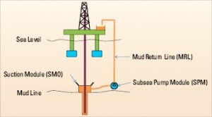
A riserless mud recovery (RMR) system (Figure 1) is in commercial use to improve top-hole drilling in water depths up to 1,800 ft (549 m). RMR uses a subsea pump module (SPM) located near the seabed to pump fluid and cutting returns from the well to the rig mud-treatment system via a mud-return line (MRL). RMR enables treatment and re-use of the drilling fluid, allowing economic use of costlier, more inhibitive fluid systems; volumetric monitoring of the well for gains or losses; gas detection; and collection of cuttings for geological evaluation.
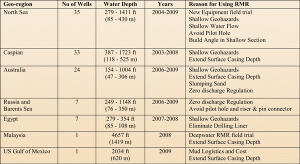
The shallow water version of RMR has been used commercially since 2003 on more than 100 wells worldwide. The most common reasons for using the system include:
• To maintain stability of shallow formations by allowing economic use of an inhibited water-base drilling fluid, which is returned to surface, treated and re-used.
• To control shallow water and gas by applying a quality weighted mud system and thorough volume monitoring, thus allowing detection and reaction via mud weight to control the influx.
• To extend depth of surface casing by improving the borehole quality through economic use of a more effective drilling fluid, maintaining appropriate borehole pressure by adjusting mud weight based on gains/losses observed, and reducing the logistical requirement to transport large volumes of disposable mud.
• Conformance to environmental regulations by providing a practical alternative to a riser and pin connector to meet “zero discharge” regulations.
Prior to establishing the joint industry project (JIP) that developed this system, shallow-water RMR was limited to approximately 1,800-ft (549-m) water depth by the practical limits of the flexible MRL hoses and providing sufficient power to pump fluid returns from deeper water depths.
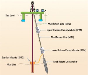
Shell, BP America, DEMO2000 and AGR formed a JIP to develop a deepwater version of RMR. This followed an earlier DEMO2000 JIP 6, which developed a jointed steel tubular as the MRL and conducted a field trial in 2004 in harsh North Sea winter weather. The deepwater RMR JIP used the same jointed steel return line philosophy and improved the pumping power, environmental resistance and deployment system to lift the return mud and cuttings from greater depths. Deepwater RMR uses two subsea pump modules (SPMs), each three pump stages, one near bottom and one near mid-water depth (Figure 2).

A deepwater RMR field trial was conducted in late summer 2008 in the South China Sea, supported by the original JIP participants and PETRONAS as partner. Deepwater RMR offered several advantages for this well:
• Overcoming mud logistical limitations: The volume of disposable mud that could be built and transported with the existing infrastructure limited surface-casing depth. Recirculation of the mud allowed extension of the shallow-casing depth such that a weak zone traditionally drilled with significant losses of synthetic oil-based mud could be cased and cemented prior to running the BOP and riser.
• Safely drill potential shallow hazards: The volume-monitoring capability with RMR allows safe drilling of shallow hazards, preventing large influxes by adjusting mud weight based on small gains/losses observed. These shallow hazards included a hydrate zone with possible hydrocarbon accumulation below and a possible shallow gas zone.
• Provide detailed mud logging through shallow hazards: Detailed monitoring of returns for hydrocarbon content (mud gas spectrographic analysis) aids planning of casing requirements to control shallow hazards in future wells.
EQUIPMENT, PROCESSES
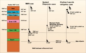
The casing plan for the deepwater RMR field trial (Figure 3) addressed several challenges:
• Set surface casing across Zone 4: Placing surface casing across this zone improves the economics of the well by minimizing losses of oil-based mud into the weak Zone 4. Using seabed dispersal of water-based fluid, the depth to which the 13 3/8-in. surface casing could be set was limited by mud logistics.
• Control possible shallow gas in Zone 1: Drill through gas hydrate layer at top of Zone 1 and control possible shallow hydrocarbons below. The risk of uncontrolled well flow is lowered with RMR as volume monitoring and precise control over the mud weight in the well is possible. The seabed discharge case for this well included a contingency shallow set of the 13 3/8-in. casing to isolate Zone 1.
• Control possible shallow gas in Zone 2: Drill through and control known shallow gas in Zone 2, with a similar reduced risk due to better volume control and improved control over mud in the well with RMR.
• Control losses while drilling Zone 3: Control likely losses while drilling Zone 3 without causing flow from Zones 1 or 2.
RMR EQUIPMENT
The deepwater RMR equipment used to accomplish the goals on this well is shown in Figure 2.
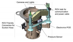
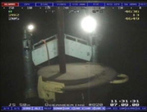
• The suction module (SMO) is mounted on the low-pressure wellhead on surface and run with the jet and drill-ahead string. The cylindrical open-topped SMO receives the return mud and cuttings as they exit the wellhead. The SMO provides a connection point for the suction hose and has provisions for monitoring the height of mud in the SMO. By controlling the height of the mud in the SMO to a constant level, mud and cuttings are returned to surface at the same rate as they exit the wellbore. The level of the mud is monitored both with redundant lighted cameras and a pressure transducer sensing the hydrostatic pressure of the column of mud in the SMO.
• The subsea electronics package (SEM) houses the SMO electronics in a lightweight frame with buoyancy to further reduce submerged weight. The SEM is transported to the sea bottom on the lower SPM and is moved to the SMO by the ROV. This method avoids exposure of the electronics to possible damage from vibrations and shock loads while the conductor casing is jetting in with the SMO mounted.
• The suction hose provides the flow path between the SMO and the lower docking joint (LDJ). The submerged suction hose weight is reduced with buoyancy to allow for easy installation with the ROV.
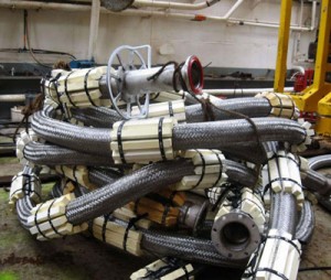
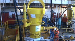
• The LDJ (Figure 4) is mounted in-line with the MRL and provides for both structural connection of the lower SPM to the MRL and connection of the suction and discharge lines for the SPM. In addition to allowing for easy mounting of the SPM to the MRL at surface, the LDJ also provides the connection point between the MRL anchoring system and the MRL. The LDJ contains a tapered stress joint at the top end to minimize fatigue damage due to vortex-induced vibration (VIV).
• The MRL anchoring system fixes the bottom end of the MRL to the seabed, holding the MRL away from the well and drillstring to avoid clash. The MRL anchoring system is not designed to restrain the MRL from vertical movement, only horizontal movement to maintain the MRL at a constant distance from the wellhead (Figure 5).
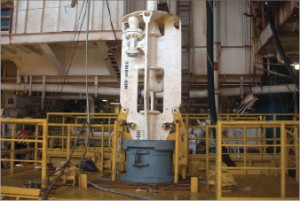
• The lower SPM contains three electrically driven disc pumps that allow for pumping of the cuttings-laden return mud with minimal damage to the cuttings. The disc pumps allow for passage of particles up to 2-in. (50.8-cm) diameter. The lower SPM mounting to the LDJ, which provides both structural and suction and discharge connections for the pumped fluid, is performed at surface using the SPM handling frame.
• The MRL provides the conduit from the seabed to surface for the return fluid and sufficient strength to support the two subsea pump modules and anchor mass and resist forces caused by currents and vessel movements. A jointed tubular, 7 5/8-in. casing with Hydril 563 connection for this well is used for MRL on the deepwater RMR. The MRL is anchored to the seabed by the MRL anchoring system and is hung off at surface on the hang-off joint (HOJ) landed in the hang-off module (HOM).

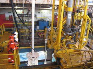
• The upper docking joint (UDJ) is mounted in-line with the MRL near mid-water depth and provides for structural connection of the upper SPM to the MRL, connection of the suction and discharge lines for the SPM, and safe, convenient installation of the upper SPM at surface. The UDJ contains tapered stress joints top and bottom to minimize fatigue damage due to VIV.
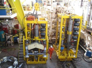
• The upper SPM, similar to the lower SPM, contains three electrically driven disc pumps to boost the cuttings-laden return mud with minimal damage to the cuttings. The upper SPM connection to the UDJ, which is performed at surface using the SPM handling frame, provides a firm structural and both suction and discharge piping connection for the pumped fluid.
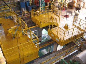
• The SPM handling frame is used to move the SPMs to the moonpool center for mounting to the docking joints. This frame was also used to hang off the MRL anchor system and the jet and drill-ahead conductor casing during deployment.
• The HOM is used to support the MRL by the HOJ at surface.
• The HOJ includes a gimbal to reduced bending moment applied to the MRL at surface due to vessel pitch and roll, and a tapered stress joint to reduce fatigue accumulation due to that bending moment and VIV.
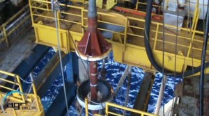
•The flowhead provides for valving to isolate the MRL from the low-pressure hose to the rig’s mud-processing equipment and facilitate connection of the contingency line.
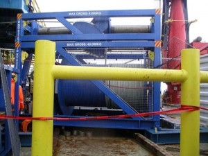
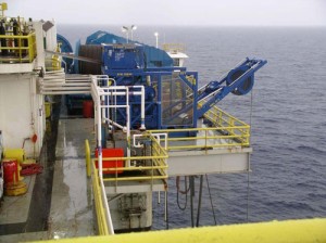
• A 25-ton winch was used to store and handle the umbilical, providing power and communication to the lower SPM and SEM.
• A 10-ton winch was used to store and handle the keel-hauled umbilical, providing power and communication to the upper SPM.
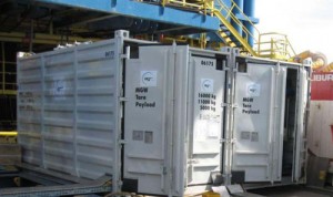
• The control containers house the communication and power equipment used to control the SPMs. This equipment includes variable speed drives (VSDs) to control the pump rate of the SPM and transformers to increase the voltage of the electricity transmitted subsea.
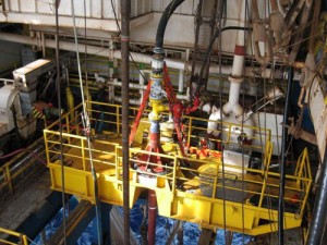
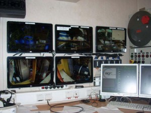
• The office and workshop container houses a workshop and spares storage area, as well as the computerized process control system that acquires the data from the sensors on the SEM and SPM and sends the signals to control the VSDs such that the pump rate of the SPM matches the return rate of the drilling fluid and cuttings.
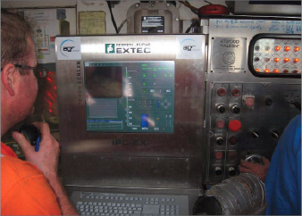
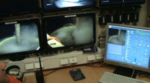
• The control system provides for operation of RMR from a panel on the rig floor during drilling operations (Figure 6). This panel is mounted in the driller’s cabin to facilitate communication between the driller and RMR operator. A redundant control panel and additional monitors are in the office and workshop container and used to monitor the health of the system during operations and is used to control the equipment on deck during rig-up and deployment.
• Auxiliary diesel-driven portable generators were used to provide the electrical power required by the system due to limited power on the vessel.
• The conductor casing hang-off frame was modified such that cement ports were manifolded together so that mud and cement could be returned to surface after the surface casing hanger was set. The cement ports were then connected to the suction port of the SMO with an isolation valve to allow easy changeover of returns when the surface casing hanger was set.
RMR DEPLOYMENT
Deployment of the deepwater RMR equipment was performed as follows:
Deployment of MRL and SPMs
1) Umbilical from 10-ton winch for powering the upper SPM was keel-hauled into the moonpool and terminated to the upper SPM.
2) Anchor piling was hung off in the moonpool on the SPM handling frame.
3) Anchor mass was run into anchor piling using synthetic rope and hung off in anchor piling.
4) Lower docking joint was run into the moonpool, connected to the anchor synthetic rope and locked to the anchor.
5) Lower SPM was mounted on LDJ.
6) Suction hose was connected to the LDJ and hung off on the MRL.
7) MRL was run, and the umbilical to lower SPM from 25-ton winch was strapped to the MRL to prevent drifting with current.
8 ) Upper docking joint was installed in the MRL.
9) Upper SPM was mounted to the UDJ.
10) Additional 7 5/8-in. casing MRL was run while the umbilical to upper SPM from the 10-ton winch was run with some slack.
11) Anchor was test-stabbed into seabed, and space out was made.
12) Hang-off joint and gimbal were installed in the MRL.
13) Anchor was stabbed into seabed, and the LDJ was released from anchor with ROV assistance.
14) MRL was hung off by hang-off joint on hang-off module.
15) Flowhead, mud flowline and contingency line were connected to flowhead.
Deployment of suction module
1) Conductor casing run and hung off on modified conductor casing hang-off frame on SPM handling frame in the moonpool.
2) Suction module, including loop to allow return of fluids to surface during cementing after casing hanger is set, was installed on conductor casing.
3) Drilling assembly and cam-activated drill ahead (CADA) tool was installed in conductor casing.
4) Conductor casing was jetted in with SMO mounted on low-pressure wellhead.
Subsea connections required
1) The ROV was used to install the suction hose to the SMO.
2) The ROV was used to install the subsea electronics module (SEM) and flying lead, providing power and communication for the SMO electronics from the lower SPM.
The RMR system is then tested by pumping seawater back to the pits from the SMO.
OPERATION OF RMR
Initial setup of the equipment requires the well to be circulated to mud. The SMO/SEM is then calibrated with a high and low level on the pressure transducer, using the cameras to observe the mud level.
During operations, the level of the SMO is maintained by the process-control system based on the pressure sensor reading. During connections, the pumps will automatically slow to maintain the static column of fluid without moving the fluid.
For cementing, after the casing hanger is set, the valve to the cement ports is opened, allowing communication of the return fluids with the SMO sensors.
DATA AND RESULTS
Drilling the well
The conductor casing was jetted in as a routine operation with the SMO mounted on the low-pressure wellhead and returns from the jetting operation taken over the top of the SMO. The cam-actuated drilling tool was tripped out to minimize risk of plugging the conductor housing with cuttings while the suction hose and SEM were installed on the SMO with the ROV.
The well was circulated to drilling mud, and the RMR system was calibrated. Drilling of the 17 ½-in. hole section was performed with returns to the shakers, with full pit volume monitoring in a similar manner on surface to drilling with the marine riser in place. During the drilling of the 17 ½-in. section, the following events related to return of the drilling fluids and cuttings and the use of RMR were experienced:
• Losses/gains were not experienced in the possible faulted section above Zone 1, and drilling proceeded with planned mud weights, flowrates and ROP.
• Hydrates in Zone 1 were drilled without incident. Methane was detected by a gas chromatograph during drilling of the hydrate zone; free gas was not experienced. Below the hydrate zone, more complex hydrocarbons were detected in the mud gas on the gas chromatograph, but free gas and high levels of mud gas were not detected, confirming the absence of a significant shallow hazard in Zone 1.
• Zone 2 was drilled with planned mud weight. Hydrocarbons were detected in drill gas, but free gas was not seen. The absence of shallow gas hazard in Zone 2 was confirmed by logging while drilling (LWD).
• Cuttings during the shale section between Zones 2 and 3 were soft but effectively separated at the shakers. Flowrate and drilling rate were controlled to remain within the shaker capacity of the vessel.
• During drilling of Zone 3, significant losses of mud to the formation were experienced. Lost-circulation material (LCM) improved the losses, and the mud weight was reduced below planned mud weight to control losses. The adjustment of mud weight was performed slowly to avoid influx from Zones 1 and 2.
• More sand stringers than expected were encountered in Zone 3. The return sand caused some blinding of the shaker screens, and whole mud was lost over the shakers. Changing the shaker screens to a finer mesh reduced the blinding of the shakers and loss of whole mud to a manageable level.
• Shortly after the LCM was pumped during losses in Zone 4, a semi-solid mass was observed at the SMO in the returns from the well. This mass, which may have been gumbo, LCM or a combination of the two, was undesirable to take back over the shakers. The RMR pumps were slowed, and the mass was dumped to sea over the top of the SMO. A portion of this mass remained on the top of the SMO, partially obscuring the camera’s view of the mud/seawater interface from the cameras mounted on the SMO.
• Cuttings from the shale section between Zone 3 and Zone 4 became progressively firmer as the well was drilled deeper and separated well from the drilling fluid at the shakers.
• More sand stringers were experienced in Zone 4 than were expected. Drilling continued through Zone 4 with intermittent losses, which were cured using LCM and mud-weight adjustments. Drilling continued through Zone 4 until a combination of LWD and cuttings analysis indicated that an appropriate casing point had been reached. The surface casing was set according to geologic evaluation at 7,404 ft (2,256 m), 169 ft (51 m) shallower than planned depth.
• During pre-job planning, there was some concern about build-up of low-gravity solids (LGS) in the mud. Significant LGS was not experienced, but this may have been influenced by the amount of fresh mud built, due to losses of mud downhole and whole mud over the shakers during the sand blinding of the shakers.
• The inhibition level of the mud was monitored by observing the salt concentration of the KCl/glycol mud. Salt concentration reduced as the mud was recirculated but was rebuilt relatively easily during drilling by addition of KCl to the mud.
• The hole was gauged occasionally during drilling by pumping carbide slugs back, calculating the average hole volume based on the volume to detection of carbide gas in the return mud stream. Gas was detected in the return fluid for about half of the carbide slugs pumped. Slugs of slightly more dense fluid were also used to gauge the hole, with detection of returns on a densitometer at surface. This method was more reliable than the carbide slugs. Average hole size at completion of the section was 18.4 in. with use of a 17 ½-in. bit.
Surface casing and cement
• The excess cement volume for the surface-casing cementation was reduced from 200% to 100% based on the good condition of the hole.
• Surface casing was run routinely with returns during running and circulation to surface.
• Losses were experienced during cementing; the loss time and volume was measured by pit volume of returned fluid.
• Traces of cement were pumped to surface and detected at the shakers. In this area, it is very uncommon to achieve cement to surface during surface-casing cementing.
Next hole section
• With the surface casing set across Zone 4, the following 12 ¼-in. section was drilled faster than previous wells, with minimal losses of oil-based mud.
PERFORMANCE OF RMR
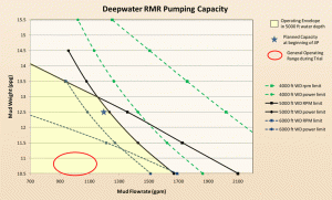
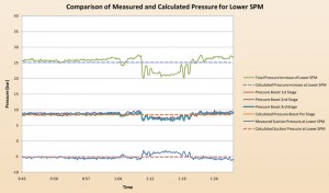
Deepwater RMR performed as expected, returning mud and cuttings at the flow rates and mud weights used during the drilling process without issues. The pumping demands of the field trial were well within the capacity of the system. Analysis of data showed that the pressures experienced by the pump units were as predicted by the pumping hydraulic model.
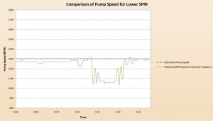
The rotational speed required to perform the pumping during the field trial was slightly lower than that predicted by the modeling, indicating that the disc pumps were generating approximately 2% more pressure head than had been predicted.
Several new items of equipment were developed during the course of the JIP to deploy this equipment:
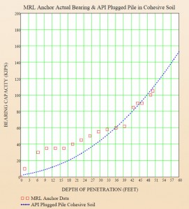
• Mud return line anchor system new development for this system. The anchoring system penetrated the soil very closely to planned depth, which was based on minimal soil information and previous jet and drill-ahead experience. No unplanned movement of the anchor was observed.
• Subsea-deployed subsea electronics module for the SMO: This was the first installation of the SMO prior to jetting of the conductor casing. Vibration measurements were performed on a jet and drill-ahead operation in the GOM, and vibrations in excess of the electronic equipment ratings were experienced. To avoid subjecting the electronics to this vibration, the electronics were packaged such that they could be deployed on the lower SPM and installed on the SMO with the ROV. This operation, which required an ROV buoyancy change with the small ROV available, was performed without incident. The electronics performed well during the operation.
• Installation of SPMs to the MRL using docking joints: This operation involved newly designed and constructed equipment and was performed as a routine operation.
• The deployment of the SPM on 7 5/8-in. casing MRL involved running the casing and two power and control umbilicals simultaneously. During this operation, there was a communication failure between the driller and the RMR operator that resulted in shearing the weak point at the bottom of the umbilical. This required pulling the SPM to surface and repairing the sheared weak point. The weak point sheared at the planned load.
• A heavy-duty single-joint compensator was mobilized to help with making up the casing joints at the lower end of the 4.5-ton upper docking joint. Some certification issues prevented use of the single-joint compensator. The driller was able to lower the UDJ with the drawworks to make up the Hydril 563 casing connection without damage or difficulty.
• While the weather during the field trial was generally mild, no movement was observed on the hang-off gimbal, even during a small squall. Post-operation fatigue analysis indicated that the tapered stress joint on the hang-off joint performed effectively, and there was minimal fatigue accumulation in both the specialized RMR equipment and the casing used for the mud return line.
• There were no cooling issues with the water-cooled electrical equipment, but the alarm for high cooling water temperature on the VSD caused a shutdown of the electrical equipment at the start of the operation. This was resolved by reprogramming the VSD to account for the higher inlet temperature of the cooling water in the South China Sea.
• Numerous logistical issues were overcome with shipping of equipment to Malaysia and certification of local rental equipment for offshore operation. Logistics of assembling the equipment and installing it on the rig went well.
No HSE events were associated with the deployment, drilling and recovery of the deepwater equipment.
CONCLUSIONS
1) Deepwater RMR, designed to return drilling fluids and cuttings during top-hole drilling, was effectively field-tested from a floating rig in 4,657 ft (1,419 m) of water.
2) Deepwater RMR development was accelerated by the formation of a JIP that ensured participation of each party.
3) Use of a recirculated drilling mud for the top-hole section of the well enabled surface casing to be set deeper than was logistically possible using traditional non-recirculating seabed dispersion of drilling fluid and cuttings.
4) Volume monitoring of the well allowed the mud weight to be adjusted as the well was drilled and, combined with the more effective drilling fluid, provided a more gauge hole, which reduced cementing volumes compared with historical norms.
5) Top-hole geologic information obtained from the return mud and cuttings provided improved information concerning shallow hazards in the area.
Acknowledgments: The authors would like to thank Shell, BP America, PETRONAS, AGR Subsea and DEMO2000 for their support during this project and for permission to publish these results.
References
1. Scott, Paul; Ledbetter, Sam; Chester, Rick; Powell, Don.: “Pushing the Limits of Riserless Deepwater Drilling”, AADE-05-DF-HO-30, 2006 AADE Drilling Fluids Conference, Houston, April 11-12, 2006.
2. Alford, S. E.; Campbell, M.; Aston, M. S.,; Kvalvaag, E.: “Silicate-Based Fluid, Mud Recovery System Combine to Stablize Surface Formations of Azeri Wells”, SPE/IADC 92769, 2005 SPE/IADC Drilling Conference, Amsterdam, 23-25 February 2005.
3. Frøyen, Johnny; Rommetveit, Rolv; Jaising, Hitesh; Stave, Roger; and Rolland, Nils Lennart.: Riserless Mud Recovery (RMR) System Evaluation for Top Hole Drilling with Shallow Gas”, SPE 102579, 2006 Russian Oil and Gas Technical Conference, Moscow, 3-6 October 2006.
4. Brown, J. D.; Urvant, V. V.; Thorogood J. L.; Neftegaz, Elvary; and Rolland, N. L.: “Deployment of a Riserless Mud Recovery System Offshore Sakhalin Island”, SPE/IADC 105212, 2007 SPE/IADC Drilling Conference, Amsterdam, 20-22 February 2007.
5. Hinton, Andy; Eikemo, Bernt; Tilley, Vince; Nolan, Tom.: “Taming the Grebe Sand – Tophole Drilling Success in the Ichthys Field”, SPE 121439, 2009 SPE Asia Pacific Oil and Gas Conference, Jakarta, 406 August 2009.
6. Stave, R.; Farestveit, R.; Høyland, S.; Rochmann, P. O.; and Rolland, N. L.: “Demonstration and Qualification of a Riserless Dual Gradient System”, OTC 17665, 2005 Offshore Technology Conference, Houston, 2-5 May 2005.
SPE/IADC 130308 was presented at the 2010 SPE/IADC Managed Pressure Drilling and Underbalanced Operations Conference & Exhibition, Kuala Lumpur, Malaysia, 24-25 February.
