BP plans for significant growth in deepwater Gulf of Mexico
BP has announced that it has approved a major expansion at the Atlantis field in the US Gulf of Mexico and has also identified significant additional oil resources that could create further development opportunities around the production hubs it operates in the region.
The $1.3 billion Atlantis Phase 3 development is the latest example of BP’s strategy of growing advantaged oil production through its existing production facilities in the Gulf of Mexico. The approval for this latest development comes after recent BP breakthroughs in advanced seismic imaging and reservoir characterization revealed an additional 400 million bbl in place at the Atlantis field.
Application of the same technology and analysis has now identified an additional 1 billion bbl in place at the Thunder Horse field. Elsewhere, two new discoveries near the Na Kika production facility could provide further tie-back development opportunities.
“BP’s Gulf of Mexico business is key to our strategy of growing production of advantaged high-margin oil. We are building on our world-class position, upgrading the resources at our fields through technology, productivity and exploration success,” Bernard Looney, BP’s Upstream chief executive, said.
“And these fields are still young – only 12% of the hydrocarbons in place across our Gulf portfolio have been produced so far,” Mr Looney said. “We can see many opportunities for further development, offering the potential to continue to create significant value through the middle of the next decade and beyond.“
BP approves Atlantis expansion
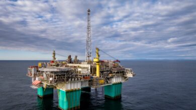
Atlantis Phase 3 will include the construction of a new subsea production system from eight new wells that will be tied into the current platform, 150 miles south of New Orleans. Scheduled to come onstream in 2020, the project is expected to boost production at the platform by an estimated 38,000 BOE/d gross at its peak. It will also access the eastern area of the field where the advanced imaging and reservoir characterization identified additional oil in place.
“Atlantis Phase 3 shows how our latest technologies and digital techniques create real value – identifying opportunities, driving efficiencies and enabling the delivery of major projects. Developments like this are building an exciting future for our business in the Gulf,” Starlee Sykes, BP’s regional president for the Gulf of Mexico and Canada, said.
“BP’s Gulf of Mexico business is key to our strategy of growing production of advantaged high-margin oil. We are building on our world-class position, upgrading the resources at our fields through technology, productivity and exploration success,” Mr Looney said.
Advanced seismic imaging boosts Thunder Horse resources
The proprietary algorithms developed by BP enhance a seismic imaging technique known as Full Waveform Inversion (FWI), allowing seismic data that would have previously taken a year to analyze to be processed in only a few weeks. Application of this technology and reservoir characterization has now identified a further 1 billion bbl in place at the Thunder Horse field.
BP’s leadership in seismic acquisition and imaging is a result of sustained investment in technology and high-performance computing. Following a successful field trial at the Mad Dog field, further advanced seismic imaging with ocean bottom nodes and BP’s proprietary Wolfspar seismic acquisition source is being planned for Thunder Horse and Atlantis to better understand the reservoirs. Wolfspar uses ultra-low frequencies during seismic surveys, allowing geophysicists to see deeper below salt layers and enabling better planning of where to drill wells.
Discoveries and new potential near Na Kika
BP is also announcing two oil discoveries in the Gulf of Mexico, at the Manuel and Nearly Headless Nick prospects.
The Manuel discovery is located on Mississippi Canyon block 520, east of the BP-operated Na Kika platform. The well encountered oil pay in high-quality Miocene sandstone reservoirs. BP is expecting to develop these reservoirs via subsea tieback to the Na Kika platform. BP’s partner in the Manuel discovery is Shell, which holds a 50% working interest.
BP also has a stake in the Nearly Headless Nick discovery located on Mississippi Canyon block 387, operated by LLOG. The well encountered oil pay in high-quality Miocene sandstone reservoirs and is expected to be tied back to the nearby LLOG-operated Delta House facility. BP’s partners in the Nearly Headless Nick discovery include LLOG, Kosmos Energy, and Ridgewood Energy. BP holds a 20.25% working interest.
Growing production in the Gulf of Mexico
Over the last five years, BP’s net production in the Gulf of Mexico has increased by more than 60%, rising from less than 200,000 BOE/d in 2013 to more than 300,000 BOE/d today. BP is currently the top oil producer in the Gulf and anticipates its production growing to around 400,000 BOE/d through the middle of the next decade.
The growth will be supported by recent project startups, including Thunder Horse Northwest and Thunder Horse South expansions and the Thunder Horse Water Injection project, as well as the addition of a second platform (Argos) at the Mad Dog field, which is on budget and on schedule to come online in late 2021.
Future potential developments at BP’s offshore fields in the Gulf include Atlantis Phase 4 and 5, further developments at Thunder Horse, Na Kika subsea tiebacks and Mad Dog field extensions.