The ABC’s of RFID: physics, oilfield usage
Understanding of antenna frequencies and topologies, how they impact performance help to tailor solution for oil/gas industry
By Ted Christiansen, National Oilwell Varco; and Jim Reed, Optimal Designs

Radio frequency identification (RFID) dates back to the late 1940s with a landmark paper by Harry Stockman titled “Communication by Means of Reflected Power,” where he described a device to aid in the identification of aircrafts – friend or foe. Non-military application of RFID gained momentum in the last 20 to 30 years as the availability of small, low-cost semiconductors (chips) for the tags became possible.
RFID is used in virtually every industry, and new applications to solve old problems are envisioned almost daily. The use of RFID in oil and gas is increasing as well, but there have been challenges because of the physical environment in which these systems would operate.
An RFID system uses tags attached to physical objects or inventory to be identified. The tag includes a small RF transmitter and receiver, as well as a circuit chip to store the encoded data. RFID tags can be battery-assisted or passive, the latter using radio energy transmitted by the reader as its energy source. An RFID reader, which is a two-way radio transmitter-receiver, transmits an encoded radio signal to interrogate the tag. The tag receives the message and responds with its identification information. The response could be a serial number, product date, etc. The reader typically relays this information back to a computer database.
The Questions
Several questions should be considered in formulating an RFID solution, and each question cannot be answered isolated from the other questions. The first thought in selecting an RFID solution might be inquiring about the tag size, with consideration of the available surface area to mount the tag.
The tag size and performance is related to its frequency of operation. Further, the frequency selected can play a factor in the success of the RFID solution, including how the RF waves interact with physical objects, as well as the communication rate and distance with the reader. Suppose the RFID frequency has been selected, and the tag size and antenna performance are satisfactory.
The next step is to evaluate the best location to mount the tag for communication performance with the reader, and assessment of how the performance of the tag changes with the mounting surface. Changes because of the mounting surface can include resonance shift, bandwidth reduction and far-field degradation, which affect the tag’s ability to communicate with the reader.
The objective of this article is to address these questions and expand on the physics behind them, with the intent of educating and empowering the RFID novice with enough knowledge to make wise decisions in creating a tailored RFID solution. A rudimentary description of an antenna will be provided, followed by an overview of available RFID frequencies, which answers the first big question.
The Antenna, RFID Frequencies
In a simple definition, an antenna converts time-varying current to propagating electromagnetic fields, the latter often referred to as radiation, far field or RF fields. The time-varying current is usually implemented as a periodic sine wave, and its periodicity defines the frequency of operation. With the law of reciprocity, an antenna can receive RF fields and convert them back to current with the same level of efficiency as in transmit mode.
To picture how an antenna works, think of it as part of an electrical circuit. There is a source with drive impedance, transmission lines, maybe a matching circuit, and finally the terminals of the antenna. The terminals of the antenna can be seen as impedance with a resistive real term and reactive imaginary term. The resistive real term at the antenna terminal is called the radiation resistance, and it’s based on how well the antenna geometry couples energy into radiation. It determines both the match and the bandwidth for an antenna system.
For a common 50-ohm system, the impedance should be as close to 50 ohms (resistance to electrical current) as possible. For the common dipole antenna, the radiation resistance is 36 ohms, but for electrically small antennas, the radiation resistance is a fraction of a single ohm.
There are other antenna terms that describe antenna characteristics. Directivity describes how well the radiation pattern is focused in a single direction. Depending on the reader configuration, the objective might be to have a lot of focus to read at longer distances with a smaller angle of view. Alternatively, it might be preferred to have a wider angle of view with shorter read distances.
Field orientation includes linear and circular polarization. For a linear antenna, the receive antenna needs to be oriented in the same alignment as transmit for detection. This also means that if the receive antenna is 90° rotated from the transmit antenna, there would be no detection at all. The inherent advantage of circular polarization – a rotating linear polarization – is that detection would occur at most angles of observation.
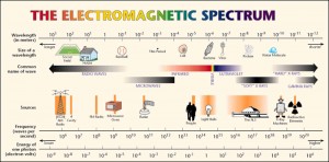
The FCC has defined Industrial, Scientific and Medical (ISM) radio bands, which apply to frequencies available for RFID technology from 6.780 MHz to 5.800 GHz. ISM frequencies of interest for RFID technology are 13.560 MHz, 915.000 MHz, and 2.450 GHz. These frequencies might be recognized, like 915 MHz for cellular technology and 2.45 GHz for Bluetooth and the microwave.
RFID: 4 big questions to ask
1: What fundamentally is an antenna, and what RFID frequencies are available?
2: What are the trade-offs for different antenna topologies?
3: What frequency should I use for my operating environment?
4: What changes in performance occur when the tag is mounted to the surface?
Antenna Topologies, Electric and Magnetic Field Coupling
There are several topologies of antennas, including wire, aperture and microstrip. At 915 MHz and 2.45 GHz, which represent the higher RFID frequencies, a microstrip or patch design is often used to create a quarter- or half-wavelength antenna. Antennas of this electrical size should have excellent radiation resistance and directivity with considerable representation of both electric and magnetic fields.
Lower-frequency RFID devices at 131 KHz, 13.56 MHz and below use a wire configuration in the form of a loop or sequential loops to create a coil. These low-frequency configurations have the electrical length of much less than a tenth of a wavelength, which places them in the unique category of electrically small antennas with very low radiation resistance and low directivity. Because they are not a natural resonating structure, a circuit is needed to tune the reactance to the desired frequency.
It is also common to load the core of these coils with a high-permeability ferrite to increase the flux density and radiation resistance. These low-frequency coil topologies have mostly magnetic field representation.
Whether the antenna primarily uses magnetic field could be an important design criteria based on the environment the tag will be used. Electric and magnetic fields act very differently in the presence of metals and liquids. Magnetic fields are less influenced by losses in liquids since liquids rarely have magnetic material losses. And by boundary condition, magnetic fields move tangentially to iron ore metal surfaces; this means the magnetic fields try to move around metal surfaces. Additionally, magnetic fields can pass through thin metals that do not have iron ore, such as tin and copper.
Electric fields are the opposite. They have high electric losses in liquids, and by boundary condition, electric fields move toward an orthogonal alignment to metal surfaces, which would have the appearance of termination.
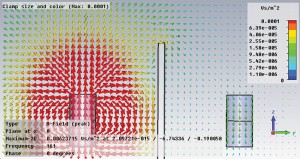
The example in Figure 2 shows how the magnetic fields travel in the presence of a steel plate. On the left is the source, a ferrite-loaded coil antenna; on the right is an identical receive antenna, and in the middle is a steel plate. It can be seen how the magnetic fields travel tangentially to (along) the steel plate, instead of terminating orthogonally (directly at) as electric fields would. The magnetic fields even bend around the edge of the steel plate and come down the opposing side to couple to the receive antenna.
This convenient behavior does not happen with electric field antennas operating at higher frequencies, i.e., 915 MHz or 2.45 GHz.
For RFID applications, increasing the frequency of operation has the advantage of superior antenna performance in read range and radiation resistance (natural resonant antennas vs electrically small antennas) and increasing the data rate of communication (more cycles per second). However, the higher the frequency, the more the RF fields can be affected by the operational environment.
When considering frequency and wavelength and their influence on physical objects, it helps to view objects as a percentage or multiple of a wavelength. The higher wavelength multiple of a physical dimension, the more “resolution” it has at that frequency, hence becoming more “visible.” Sometimes the goal might be for the object to be visible, and other times it may not.
One example is the walls of buildings; 915 MHz will pass through building walls better than 2.45 GHz because the wall is only half of a wavelength in depth at 915 MHz but almost two wavelengths at 2.45 GHz. Another example is the reading of a tag inside packaging material that is very “lossy” at 2.45 GHz but have no effect at 915 MHz. Thinking about how the proposed frequency of operation will interact in the working environment will help in choosing an RFID solution.
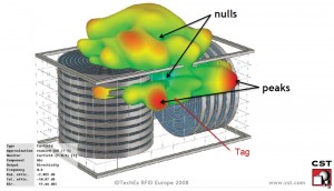
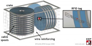
Figure 3 shows a 915 MHz RFID tag placed in a complex environment and the resulting “read angles” available from the far field pattern. This exemplifies how the environment can change the RFID performance.
RFID technology by the numbers
- ISM frequencies of interest for RFID technology are 13.560 MHz, 915.000 MHz and 2.450 GHz.
- At 915 MHz and 2.45 GHz, which represent the higher RFID frequencies, a microstrip or patch design is often used to create a quarter- or half-wavelength antenna.
- Lower-frequency RFID devices at 131 KHz, 13.56 MHz and below use a wire configuration in the form of a loop or sequential loops to create a coil.
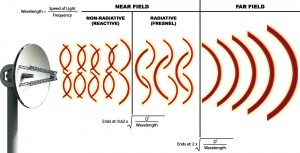
The electromagnetic field around an antenna can be separated into two primary field regions, near field and far field. The near field encompasses the immediate reactive field region; “reactive” implies that external changes to the field in this region have a “reaction” on the source. Still in the near field but decoupled from the antenna is the Fresnel region. And the far field begins where the near field ends, with the common mathematic approximation of 2D^2/wavelength, where D is the maximum dimension of the radiating surface and wavelength is defined by the frequency. Figure 4 shows these three regions.
As mentioned, external field perturbations in the reactive field region, such as dielectric loading or shunt capacitance from a grounded metal surface, can detune the antenna. Other concerns for mounting a tag on a surface is shielding of the antenna far field pattern, which limits the tag’s ability to communicate with the reader.
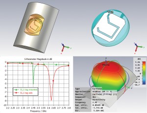
Figure 5 shows an example of how antenna performance changes when mounted. The tag in free air is shown on the right and mounted in a machined pocket in metal on the left. The bottom-left panel shows the tag antenna’s response vs frequency, where the red curve is the tag in free air, and the green curve is with the tag mounted in the metal substrate.
Note that the red curve – tag in free air – is deeper (better match) and wider (more bandwidth) than the green curve – tag mounted. Recall both match and bandwidth are related to the radiation resistance of the antenna. It should also be noted how the frequency changed from 2.625 GHz to 2.45 GHz. These three changes – match, bandwidth and center frequency – are typical of what happens when a tag is mounted in the presence of metal. The initial antenna was tuned to 2.45 GHz in the metal mounted environment. The solution to this problem is to tune the tag to operate on the intended mounted environment.
This is a case where one tag for both free air and mounted is simply not possible; the physics do not allow it.

Real-World Environment Example – Stacked Pipe
Imagine drill pipe stacked on a trailer being transported from a pipe yard to the well site. Wouldn’t it be great if the truck could drive through the gate and all the pipes were scanned automatically? This is a commonly suggested idea, and sounds great in theory; yet it is difficult to achieve in practice. Examining this situation in more detail helps to understand why.
To visualize how the radio signals travel between the tags and the antenna, imagine placing a flashlight at the location of the RFID tag on the pin end tooljoint, perpendicular to the tag. Imagine the light traveling in a straight line, with some diffusion in a conical shape. Suppose there is a “wall” of antennas on both sides and the top of the trailer. The antenna panels are going to receive light only from flashlights that are aimed toward them, where the light is not blocked by an adjacent drill pipe.
Further, the strength of light received varies as a function of the angle between the flashlight and the solar panel. The light from flashlights pointing directly at the trailer’s bed will not be received. The spacing of the joints does have an influence but has limits of practicality because the stack would become too tall. Higher-frequency RFID solutions act like the flashlight analogy so it can be concluded that it will not work for this application.
Low-frequency RFID inductor topologies with a majority of field strength in the magnetic field (RuBee, LF, HF) have an advantage, where line of sight is not needed since magnetic fields are able to bend around adjacent joints. With a properly designed inductive antenna and the appropriate technology (RuBee, LF), this scenario is possible.
Conclusion
In this article, along with the background of what consists of an RFID system and a description of antenna characteristics, the trade-offs of RFID frequencies and geometry topologies were discussed, and the importance of understanding both the reader-to-tag operating environment and the tag mounting environment was emphasized. Lastly, a complicated real-world example in the oil and gas industry was examined to determine if it is possible.
It is clear that RFID has the potential to improve many processes in this industry. However, the challenges in the oil and gas environment – metal, environmental conditions – make the choice of technology difficult. More importantly, the judicious application of RFID in oil and gas must be based on the physics of RFID. When the application of RFID to a real-world scenario is considered, the question should be asked whether the physics support it. If not, there may be another way to solve the problem. This alternative solution may not be flashy or leading edge, but it might just get the job done.
References:
http://en.wikipedia.org/wiki/ISM_band
H. A. Wheeler, “Small Antennas,” IEEE Trans. Antennas and Propagation, Vol. AP-23, No 4, July 1975
http://autoidlabs.eleceng.adelaide.edu.au/Tutorial/1356RFID.pdf
http://cst.com/Content/Documents/Articles/article438/Marc_Ruetschlin_CST_RFID_Europe_2008_online.pdf




The RFID tagging of assets in Drilling Companies can be very useful however operational extremities of involved components make this innovation less popular until there are more technological improvement.
Awaiting further developments. Nabors Canada and SLB have seen some success with RFID tagging.
Performance Engineer (Drilling)
How would someone apply this to an assembly of parts?
This may work on pipe or parts with out many components but larger assemblies would require you to reprogram the chips with a list of parts in that assembly every time and may be a problem.