Plume modeling study quantifies risk of H2S release in exploration drilling
By Michael Bates, Risktec Solutions
With the increasing likelihood of exploration wells being located near population centers in the Middle East and elsewhere, an evaluation of the risk of an uncontrolled release of toxic gas reaching such a settlement needs to be quantified. A plume (gas cloud) modeling study has been completed to determine the level of H2S away from an exploration well.The quantified risk assessment (QRA) involves identifying a range of potential major accident hazards associated with drilling operations and is described numerically as the location-specific individual risk (LSIR). LSIR is associated with a hypothetical individual who is positioned at a location for 24 hours a day, 365 days a year. It is calculated by considering the frequency of an event multiplied by the probability of the location being affected by each individual event, multiplied by a probability of fatality.
A number of scenarios were developed looking at different process configurations, different well fluids and different weather states. This article includes key study elements, results and identified risk mitigation actions required to reduce the risk to as low as reasonably practicable (ALARP).
Risk levels are demonstrated to be tolerable and significantly below UK HSE risk tolerability criteria. Only one of the 16 scenarios that was modeled described greater than 50 ppm H2S concentration at the location. Five scenarios suggested that the H2S levels exceed 50 ppm at the road near the well location. This result will now be put into context.
Background
Drilling operations have always had inherent risks, but now that oil and gas companies are increasingly exploring sour reservoirs, there are added risks associated with toxic components such as hydrogen sulfide. As toxic components have adverse health effects at very low concentrations, the consequences of a toxic release can be seen at significant distances from a drill site. This has implications not only for company employees but also for the public.
With exploration wells being increasingly located near population centers, an evaluation of the risk of an uncontrolled release of gas reaching such a settlement needs to be quantified. An assessment has been performed to show the physical effects (toxic dispersion) of an unconstrained flow from a well. The assessment considers the blowout frequency, the probability of blowout type (either vertical/horizontal, with drill pipe/without drill pipe) and the probability of different well fluid types.
The assessment also leads to a review of the controls required to be in place to ensure the risks are managed to ALARP. This has been performed using the bow-tie methodology.
The following key steps were followed in this study:
- An assessment of the likelihood of an uncontrolled H2S release (blowout) occurring. This was based on available global statistics combined with the author’s experience gained from other projects of similar scope. The main reference source was the Scandpower Blowout and Well Release Frequencies report to access failure rates. This also includes estimates of the probabilities of blowout types (with drill pipe and without drill pipe);
- An estimate of fluid type (using near-well exploration results);
- Computer modeling of near- and far-field H2S concentrations that would result from several release scenarios. This used FRED modeling software developed by Shell;
- An assessment of the overall toxic risk using Shell’s SHEPHERD software. The tool combines the plume modeling results (FRED), local meteorological conditions and the release frequency assessment to quantify the effect and probability of the possible consequences.
- A bow-tie (or risk and outcome) assessment to identify barriers that can be put in place to prevent uncontrolled H2S releases and mitigation measures that can be put into place to eliminate or reduce the effects of such a release.
While results described here refer to H2S, it is recognized that sulphur dioxide (SO2) could be produced if the released H2S-bearing hydrocarbon cloud were ignited since H2S is converted into SO2 during the combustion process. The modeling considers H2S to be the main toxic constituent and, therefore, the greatest risk. This was because of its primary association in the well fluid hydrocarbons and the higher probability that an escaped gas cloud would remain un-ignited.
Site Area
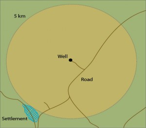
The site in question is in a desert location but with a settlement 5 km from the site and a main road 1.5 km away. Figure 1 shows the site location.
Blowout Frequency
Blowout frequencies were assessed using the Scandpower report. Well types were chosen to represent a number of exploration wells in the Middle East.
Although the Scandpower data is predominantly based on information collected in the UK North Sea and the US Gulf of Mexico, it is arguably the most complete and reliable database currently available for blowout data.
The following frequencies and probabilities have been taken from the report:
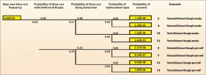
Base frequency of blowout = 5.3 x 10 per year. This refers to the rate that includes all wells drilled in the North Sea and the US Gulf of Mexico.
Probability of blowout type given blow-out:
- Outer annulus = 0.95 (95%)
- Open hole = 0.05 (5%)
Probability of blowout direction given blowout:
- Outer annulus = 49% horizontal & 51% vertical (Scandpower report has all vertical; author experience suggests this is a more realistic breakdown).
- Open well = 49% horizontal and 51% vertical
Fluid Type
Using local reservoir data and assessments of similar formations, two fluids could be expected from the well in question. However, the likelihood was for one rather than the other, so this was given a 95% probability.
The two fluids were:
- Gas condensate = 95% probability of occurrence.
- Oil = 5% probability of occurrence.
As the main focus of the assessment was to determine the risks at the settlement (i.e. far-field effects), only the gas phase of each fluid was modeled. It was assumed that the liquid phase would rain out close to the well site.
Release scenarios
Release scenarios were derived using operational data, documented probabilities and the author’s experience. Variables that were considered included:
a) Oil or gas with high H2S content – derived from experimental data for similar reservoirs.
b) Vertical or horizontal blowout of gas from the well – derived from documented probabilities and author experience.
c) Wellbore with and without drill pipe in the hole – derived from documented probabilities.
d) Wind speed and direction – derived from site-specific data.
Event Tree
Using the base frequency derived from the Scandpower report and the probability data detailed above, an event tree was developed (Figure 2). It should be noted that each event on the event tree is modeled for multiple weather states.
Consequence Analysis
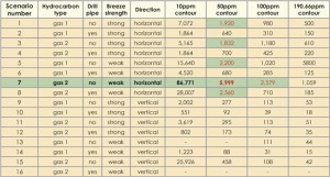
Combinations of the above data led to the development of the release scenarios in Table 1, which represent the range of possible outcomes for an uncontrolled release. The table also shows the results of the consequence analysis. It shows that the highest dispersion distances are seen from Scenario 7. An H2S concentration of over 50 ppm can be seen at the settlement, but concentrations above the lethal concentration of 190.66 ppm (LC1 for 30-min exposure) are not seen in that location.
Gas Cloud Dimensions
The gas cloud in question is a cloud containing H2S gas that has been released from operations associated with drilling of an exploratory well. The plume is described as the shape and size of the gas cloud and is considered to be a simple entity for modeling purposes. The plume size and shape is calculated within the FRED software, and this information is transferred to the SHEPHERD software for risk integration calculations. The plume calculations are simple physical calculations only as the complex behavior of such a cloud in the actual environment cannot be closely modeled within this scope of work.
LSIR
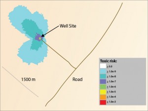
Location-specific individual risk (LSIR) is the risk to a person who is in a single location for 24 hours a day, 365 days a year. Figure 3 shows the risk results from SHEPHERD modeling from all scenarios in Table 1. The maximum distance to the 1.00E-06 toxic risk contour is 28 meters from the release location (wellhead).
Analysis, Risk Reduction
To ensure that the risks were being managed to ALARP, a bow-tie analysis was performed to identify the causes and consequences of a release.
The barriers to prevent a release were identified, as well as the threats that could lead to the consequences being realized.
The bow-tie analysis identified 12 risk reduction measures, of which 10 were recommended for immediate implementation and two were recommended for further study. The risk reduction measures were categorized as under equipment, personnel and procedures.
Equipment
Most of the issues raised referred to specific issues with the existing configuration, including alterations to the rig infrastructure and additions to associated equipment. The most immediate issue required a visit to the rig site to ensure that the side outlet valve was to be directed away from the settlement, which necessitated the site layout to be re-orientated. The choke manifold also had to be adapted so that it could be changed out in the event of failure during circulation.
A circulating device was installed to allow circulation and pressure control while running in the drillstring. Radio communications equipment was vetted and updated to allow full communication in the event of an emergency.
Personnel
Personnel measures centered on the use of a second drilling supervisor while breaking into the reservoir. This was considered essential to ensure that a senior member of staff was on site 24 hours a day who had full responsibility for emergency situations.
Procedures
The most important procedure type was the company emergency response plan. This was tested to ensure its effectiveness. Prior to the exercise, personnel had their actions and responsibilities reiterated. The exercise was monitored by both company staff and external observers, and the outcome was considered sufficient once a couple of points were clarified and their results passed back to the rig crew. Other procedures included ensuring all senior drilling staff and toolpushers took an on-scene commander course along with other identified training. All operational procedures as per the Manual of Permitted Operations (MOPO) were to be revisited for all crew and reiterated in light of the requirements.
Well control training was also recommended and took the form of simulator training at the rig. All crew were taken through a scenario that involved an influx into the well to simulate the penetration of a high-pressure reservoir. The actions of each crew member were observed and, where necessary, the correct procedure for dealing with the situation was stressed and the exercise repeated.
Risk register
A “risk register” was set up to capture all recommendations of the bow-tie analysis and to ensure that the necessary actions were assigned. Actions within the risk register were maintained by the “well owner” and available to all parties.
Results
The following results were derived from the assessment:
- At 190.66 ppm (lethal concentration threshold), no releases are predicted to reach the road (1,500 meters) or the settlement (5,000 meters).
- At 100 ppm gas 2, through open-hole (no drill pipe), weak breeze scenario is predicted to reach the road, while no releases are expected to reach the settlement.
- At 50 ppm, five of the horizontal releases but none of the vertical releases were predicted reach the road. Only one release (scenario 7) reaches the settlement – the gas 2, without drill pipe and with a weak breeze.
- Maximum H2S concentration at the settlement is approximately 60 ppm.
- A 10 ppm plume width at the settlement is predicted to be between 240 meter and 2,304 meter (scenario dependent).
- For an ignited well release (planned or unplanned), assuming all H2S converts to SO2, the 100-ppm contour for SO2 is at 2,537 meters from the well and 394-ppm contour (UK HSE 1% fatality) at 340 meters. The conclusion is that SO2 does not represent a risk at the settlement.
- A blowout bow-tie was developed that identified 12 remedial actions for the well; 10 of these were assessed by the project team as being required to be implemented immediately in order to reduce the risk to tolerable and ALARP.
- Risk levels are demonstrated to be tolerable and significantly below UK HSE risk tolerability criteria (at settlement and road).
- Distance to 1.00E-06 per year LSIR contour (UK HSE risk criterion for public) is 28 meters for all possible events.
Conclusions
Risk levels are demonstrated to be significantly below PDO risk tolerability criteria. It should be clearly noted that the worst modeled scenario involves no drill pipe in the hole, a situation that is considered highly unlikely to be within existing operational procedures. It is very unusual for any rig operation to be performed that involves pulling out of hole without bottomhole conditions being fully stabilized. This significantly reduces the possibility of dispersion of a toxic gas cloud from rig operations.
The maximum H2S concentration at the village is approximately 60 ppm (for one scenario and only if a long list of intermediate events have previously occurred).
The exploration well was considered safe to drill after a comprehensive review and the completion of a plume modeling study. The results highlighted areas where existing equipment and procedures could be improved.
The goal was to review the possible scenarios and determine their risk level and recommend mitigations. Only the most extreme scenario resulted in the plume potentially reaching the settlement at unsafe levels, but the probability of this occurring is extremely small.
The concept of managing risks to ALARP underpins operations of all major oil companies. Issues raised by this assessment were investigated and actions and/or equipment were put in place to reduce risk. This work has been referenced for subsequent operations and has demonstrated value as it permits the prompt evaluation of the risk to adjacent settlements using a standard procedure.
This article is based on a presentation at the IADC Critical Issues Middle East Conference & Exhibition, 10-11 May, Dubai.
Reference:
Scandpower, Blowout Risk Assessment of Kashagan Development Phase, Report no. 27.230.002/R1, February.
Nomenclature:
ALARP – As Low As Reasonably Practicable
ERP – Emergency Response Plan
FRED – Consequences and modelling software
H2S – Hydrogen Sulphide
HEMP – Hazards and Effects Management Process
LSIR – Location Specific Individual Risk
MOPO – Manual of Permitted Operations
QRA – Quantified Risk Assessment
SHEPHERD – Assessment of physical effects software
SO2 – Sulphur Dioxide
UK HSE – UK Health & Safety Executive

