New section milling technology designed for restricted IDs restores access to leached area of cavern in highly abrasive Texas salt dome
Tool helped to cut window in intermediate casing to access hydrocarbons trapped above casing shoe
By Michael T. Smalley, Christopher Hay, David W. Teale, and Mohammed A. Haq, Weatherford International

The Stratton Ridge salt dome in Brazoria County, Texas, has been used extensively by the industry for brining operations and for the storage of liquid hydrocarbons, refined products and natural gas. The shape of the dome has been defined by several hundred oil and gas wells drilled over the top of this highly anomalous geologic diapir structure. Cavern operations at Stratton Ridge are known to have experienced multiple problems, including severe lost circulation while drilling through cap-rock, sheared well casings, corrosion, shifting and encountering hydrocarbon products that appear to have escaped from the storage cavern.
This article describes a case study of section milling in the gas storage cavern of this highly abrasive salt dome, the challenges faced and how they were detected and overcome. The unique aspect of this case study is the introduction of a new section milling technology. New technologies in multiple-string section milling play an important role in improving operational performance, reducing costs and eliminating NPT. The article also touches on the R&D development for multi-string section milling in various settings.
Background
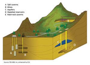
In general, there are three primary types of underground hydrocarbon storage facilities: depleted reservoirs in oil and gas fields, aquifers, and salt cavern formations in salt domes (Figure 1). Each storage type has its own physical characteristics – porosity, permeability and retention capability – and economics – site preparation and maintenance costs, deliverability rates and cycling capability – that govern its suitability for particular applications. Significant features of an underground storage reservoir include its capacity to hold natural gas for future use and the rate at which gas inventory can be withdrawn, described as its deliverability rate.
A salt dome is a column of salt that has been displaced upwards or downwards into overlying sediments and formed moundlike dome shapes. The salt-rock has the ability to flow under pressure. The salt is overlaid by thousands of feet of sediment rock layers that place tremendous pressure on the salt surface, thereby causing it to flow. At numerous locations, the salt can intrude upwards into overlying sediments, producing small mounds or towering columns of salt that can be thousands of feet tall.

These salt columns and smaller mounds – also called salt domes – are significant because they can deform rock units into traps that can hold millions of barrels of oil and natural gas. Salt domes can be used not only for storage of hydrocarbons but also as sources of sulphur and salt production, as disposal sites for hazardous industrial waste materials, and as natural repositories for storage of helium gas.
Salt caverns provide very high withdrawal and injection rates relative to their working gas capacity. Base gas requirements are relatively low. Most salt cavern storage facilities have been developed in salt dome formations located in the US Gulf Coast states.
When an operator locates a suitable salt dome or salt bed, the site is excavated to form a cavern. This process is usually done by pumping or injecting highly pressurized water into the salt layer to dissolve the salt and create a cavern. This method is sometimes referred to as cavern leaching or solution mining. After this process, the operator can remove the brine and commence operations. These salt caverns are impermeable under high pressures. Moreover, if they are excavated to certain depths, the geological pressure can help to make storage salt caverns self-healing by quickly sealing any cracks that may occur. Salt caverns account for about 23% of US daily deliverability of underground natural gas storage.
Fishing Operations and Section Milling
In oilfield operations, the term fishing means the technique to remove lost or stuck objects from a wellbore. Generally, fishing jobs fall into three classifications: open hole (when there is no casing in the area of the fish), cased hole (when the fish is inside casing) or thru-tubing (when it is necessary to fish through the restriction of a smaller pipe size or tubing).
A fish can be any number of things, including stuck pipe, broken pipe, drill collars, bits, bit cones, mud-stuck pipe, stuck packers or even dropped hand tools or other junk in the hole. Washovers, overshot runs, spear runs, wireline fishing, stripping jobs, jar runs, casing cutting and section milling are among the many fishing techniques developed to deal with the different situations. Because there are so many different kinds of fish or fishing jobs, the different tools or techniques used can vary from very simple to extremely complex. The cost effectiveness of fishing operations is imperative because all the drilling, workover or completion operations cease during fishing. Experience, good judgment, a careful analysis of the problem and effective communication among all the parties will lead to normal drilling, completion or workover operations with the least amount of lost time and revenues.
Milling tools are essentially fishing tools dressed with tungsten carbide or diamond cutters or cutting structures to mill or grind away a fish, such as stuck tools or pipe in the well. A mill can also be used to dress the top of fish, ream out collapsed casing, ream scales formed on tubulars, remove cement plugs, sidetrack to increase reservoir access, or mill out a defined section length of casing to create a window.
A section mill is used primarily for milling sections in the casing. Milling can usually be done as fast as cuttings can be circulated out of the hole. Fluid viscosity is critical, and 45 to 65 is the preferred viscosity range. Standard section mill blades are dressed with high-quality tungsten carbide composite rods and carbide inserts. Tungsten carbide slugs or rocks are suspended in matrix that is bonded to the mild steel blade, which is backup support for the tungsten carbide.
Section mills can be used to remove screens, liners and liner packers, to cut washpipe that might be stuck or to cut pipe prior to pulling. Old wells are easily plugged in underground storage areas by milling a section of casing above and below the storage formation and squeeze-cementing. The formation may be underreamed after the section is cut and may be gravel-packed after original completion.
Well Setup, Surface Equipment

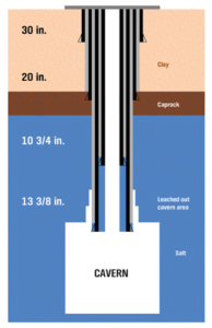
The total depth (TD) of the well in this case study was almost 3,120 ft. The salt layer was below caprock, silts and clays. The cavern had been leached out to create more than 1.5 million bbl of storage capacity. A 30-in. conductor drive pipe had been driven with 20-in. surface casing with shoe depth at about 1,000 ft. The 13 3/8-in. intermediate casing shoe depth was approximately 2,390 ft, and a 10 3/4-in. cemented liner to surface with 7 5/8-in. brine string had been set close to 3,100 ft.
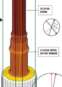
The cavern had leached behind and above the 13 3/8-in. shoe (Figure 2). This led to hydrocarbons being trapped above the 13 3/8-in. casing shoe, becoming inaccessible. The objective was to cut out a window inside the 13 3/8-in. casing and to mill downwards all the way to the shoe or until the casing stub dropped in the cavern. To do this, the 7-in. brine string was tripped out and laid down, and surface equipment was installed for milling operations to commence. The surface equipment on the workover rig included a 3.5 power swivel, RCD, BOP stack, pumps with 4- to 7-bbl/min capacity and 10.10 lb/gal brine tanks.
The 13 3/8-in. casing was perforated with six shots per foot in the section where the window was to be cut out and milled down. This required the milling operation to consist of intermittent cuts, which could potentially severely damage the carbide cutters. The body OD of traditional section mills for 13 3/8-in. casing is 11 1/4 in. Because the tool had to pass through the restricted ID of 10 3/4-in. casing, traditional section milling would not be possible. It was, thus, important to perform a field trial on the new technology being developed.
Case Study of Section Milling in Salt Dome Formation
Objectives
The objectives in the case study were as follows:
• Cut out a window in 13 3/8-in., 61 lb/ft casing, by using a DSSM 13 3/8-in. cut-out bottomhole assembly (BHA); and
• Mill down on this 13 3/8-in. casing by using a DSSM 13 3/8-in. milling BHA until the casing falls into the salt cavern.
The section milling tool to be used was an R&D tool released for field trials after having completed extensive runs at the drilling rig test facility.
The following section milling tools were available:
• A 13 3/8-in. cut-out BHA with hydraulic stabilizer tool and two sets of cut-out blades 15° blades and flat top cut-out blades; and
• A 13 3/8-in. milling BHA with hydraulic stabilizer tool and two sets of milling blades (a primary and a backup set).
Observations and Conclusions
Data for torque, pressure and weight on bit (WOB) had to be recorded manually through visual inspection of gauges. There was no gauge to record RPM and flow rates; they could be calculated by pipe rotation and pump strokes, respectively.
The first BHA was tripped in hole to target depth at 2,373 ft. Free torques were recorded as follows: 2,000 ft-lb for 96 to 112 RPM at 0 pump psi and 1,500 ft-lb for 68 to 70 RPM.
Window cut-out pump pressure at initial contact was 50 psi; torque increased when contact with the casing ID was established. Pump pressure was increased to 100 psi with 96 to 100 RPM gain in the weight indicating that the cut-out blades on the section mill were fully open. A smooth cut-out was achieved in 19 minutes with no stalls or issues.
After the cut-out operation, the fishing tool operator began milling downwards to achieve a section length window. After 2 ft of milling down, the torque dropped, and there was no drill pipe chatter at the slip bowls, which indicated that the blades were not milling down. It was necessary to pull out of hole, inspect blades and run logs downhole to make definitive conclusions. The NPT resulted from downtime for repair of mud pumps and from the inability of stiff arms on the power swivel to pass down.
After the BHA was tripped out, the blade sweep was gauged; the initial inference was that the abrasive salt had worn out the sweep OD. Earlier cement bond logs (CBL) had shown no cement behind the 13 3/8-in. casing. Wireline services were requested to run density or caliper logs to verify the milling operations. A density log was not recommended because of the risk of losing the source in the open-hole cavern and then not being able to fish out the source.
A six-arm caliper log tool was run to determine section length. Initial log readings indicated that the window section length was 2 ft, that the remaining 13 3/8-in. casing was intact and that it had not dropped in hole as previously thought. This proved that initial CBLs were not accurate and that cement and abrasive salt were present in this window section area behind the 13 3/8-in. casing.
The cavern’s formation was salt with quartz-like crystals. The physical properties data sheets for the salt indicated very high shear strengths – 70 psi at one place and 700 psi at another place. Tensile strength was noted as 100 ksi. Tripping out of hole and tool inspection revealed that salt crystals and cement debris were retrieved along with the tool.
After the service engineer reviewed the log numbers, it was found that the actual length of the completely open window section was 9 in. This was an important observation because it saved a trip to run milling blades. The logs showed a taper geometry above and below the window section. A subsequent run with a different type of cut-out blades achieved a 5-ft window length, and that was confirmed by casing collar log (CCL) reports.
A final run made with the milling blades BHA milled down 11 ft of additional section length, including one 13 3/8-in casing coupling. Milling torque was lost, and free torques were observed, indicating that the 13 3/8-in. casing remnant tube had fallen through the hole and into the salt cavern. A CCL run showed that the 13 3/8-in casing collar or coupling was not present, indicating that the casing stub had dropped into the salt cavern.
A sonar log run with wireline showed 1 ft to the left and 0.5 ft to the right, which indicated an average borehole diameter of 18 in. For placing the 13 3/8-in casing during the well construction phase, a drill bit of 17 1/2-in. OD is normally used.
The objectives had been met, and there was no need for an additional six-arm caliper log. This milling system enabled the driller to regain access to the leached area of the cavern behind the cased and cemented main bore that led to the reservoir.
Improvements in Tool Development
The field run resulted in significant observations to enhance tool performance and further develop the technology for section milling. Use of steeply tapered cut-out blades was effective for initial cutting out of the window but not for milling down for longer section lengths. The flat top cut-out blades were good for milling down longer section lengths but required more time to cut out the initial window, as was observed in rig testing. The optimal design had to be in between, and a 7 ° angle was selected and rig-tested later to prove this. Axial and radial milling upwards and outwards at directional angles were also significantly improved.
To improve wear resistance, tool steel had been used on some internal components. This was effective for wear resistance to higher flow rates or wash outs, but the tool steel proved to be brittle to severe vibrations or torque applications. Material enhancements were made to alleviate and remove this issue.
Improvements in stabilization were achieved by redefining the hardbanding process and elimination of carbide rods for stabilizer pads.
Conclusions
The key challenge of this case study was to develop a tool that would pass through the restricted ID of the inner string (7 in. or 9 5/8 in.) and make a section in the next outer string (9 5/8 in. or 13 3/8 in.) without damaging the third string of casing (13 3/8 in. or 16 in.). This technology was developed and extensively rig-tested for milling 9 5/8 in. and 13 3/8 in. casing sections.
This field run and case study were also important in further developing this technology to run through restricted-ID sections and to use a milling tool of the same size to cut sections on both the inner and outer casing strings. Thus, the dual-string section mill was further developed to mill both the inner and outer strings of casing in a single or multiple trips, allowing the operator to set a cement plug against the open hole.
By completely removing the casing, the milling run prepares the wellbores for rock-to-rock cement plugging. This plug restricts migration of hydrocarbons or micro-channeling, thus creating a more reliable and permanent seal for the life of the well. DC
Acknowledgements: The authors would like to thank Weatherford for granting permission to publish this paper and to express special thanks to Ms. Sally Helbert for reviewing the paper.
This article is based on SPE/IADC 184596, “Case Study of Section Milling Run in Abrasive Salt Dome Formation and Technological Development for Multi-String Section Milling,” presented at the 2017 SPE/IADC Drilling Conference, 14-16 March, The Hague, The Netherlands.


