Modular machine control may be next step to achieving integrated drilling control system
By Wayne Cantrell, Siemens Industry

I once had a machine manufacturer tell me that his customers purchased his machines when their budget allowed it. This resulted in several standalone machines in their factory. Each of the standalone machines had its own start/stop switch and human-machine interface (HMI) station. During startup, shutdown and production, the factory operators had to physically go to each machine to interact with it.
As a result, the manufacturer asked for a solution to integrate the operation of the machines so a single start/stop could be issued to all machines simultaneously and the operating status of all machines could be viewed from a single HMI. There was also a requirement that customers not have to modify the logic program of each machine. The setup for the coordinated execution had to be accomplished via setup screens on HMIs.
The problem was solved using a TCP/IP solution. From this exercise, Siemens coined the term “modular machine control” with this definition: “Modular machine control is coordinated control functionality by two or more autonomous machines via means of data communications or hardwired data signals.”
The concept of modular machine control has been used in the industry for several years. Specific products have been developed for high-speed communication between modular components of assembly lines. The concept is applicable to industries such as automotive, food and beverage, corrugated material management machines, oil and gas, marine vessel systems and others.
When planning for modular machine control, a few basic implementation concepts should be considered:
• Define the requirements of the control functionality:
- Define the safety requirements;
- Determine the level of coordination between machines;
- Decide which machine will be the coordinator of the control functionality;
- Determine the performance requirements for the communications between machines;
- Define, or select if it already exists, the format of the data that will be exchanged between the machines;
- Review and determine the best communication method for each machine, keeping in mind the performance and data format requirements;
• Implement the solution from the requirements definition.
• Perform proper testing of the implementation, including a thorough factory acceptance test.
• Deploy the tested solution.
When defining the safety requirement, the goal is to ensure that all machines are capable of being transitioned to a safe operating mode or safe position at any time. Consider the functionality for an emergency stop (e-stop). All machines will most likely have a local e-stop. However, is there a need for a global e-stop to stop all machines at once? How should the system react if data communications are lost? If one machine stops, how should the upstream or downstream machines react? What is the reaction time of each machine? Is the operation of the machines so critical that redundant communication paths are needed? Is it possible that the environment, such as EMI or RFI, will affect the communications? The answers to these questions will help determine the best method of communicating between machines.
Coordination of machines can take one of two forms – simple or complex. Simple coordination consists of basic data transfers, such as:
• Transferring a single start or stop command to all machines;
• Exchanging interlock information, such as, machine one is running; machine two can now start;
• Transferring operational information like set point parameters to other machines.
Complex coordination is required for more sophisticated control functionality, such as synchronized operation of machines where data must be exchanged continuously at higher frequencies. Examples are coordinating operating speeds or increasing the coolant output of one machine based on the operating temperature of a second machine.
When defining performance requirements, decide how much data and how fast the data must be exchanged between machines. The execution time of the control program in each machine plays a big role in exchanging data. If the control programs are slow, the data exchange method needs to be one that will have the data “waiting” for the next control logic cycle. A slow data exchange method combined with a slow logic program results in poor control performance. Reviewing the performance of each machine will help decide the best communication method.
When choosing the communication method between machines, a few basic concepts should be considered:
• Do the machines communicate the same protocol? If not, do commercial hardware or software gateways exist that will meet the communication requirements?
• Does the equipment, such as a PLC or PC, functionality meet the data exchange performance requirements?
• Does the environment support the communication options? For example, is there interference that could affect wireless communications?
• If redundancy is required, does the chosen protocol or communications media support it? How fast is the switchover to the backup data path?
The answers to these questions will help narrow the communication choices.
Machine controllers consist of at least two components – an input/output subsystem used for connecting to sensors and control devices, and the logic program controller execution subsystem. Additionally, an HMI or SCADA system may be connected to the controller.
Beyond that, an enterprise system, such as a production control or inventory management system, may be connected either locally or from a remote location. Any of these systems can perform the data exchange between machines.
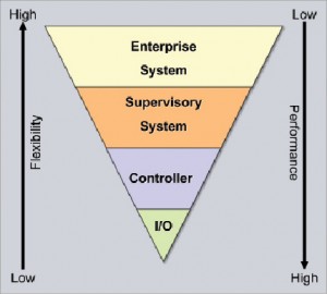
Some offer more flexibility for data exchanges, and others perform faster data exchanges. Figure 1 shows a typical comparison.
The I/O subsystem of the controller typically has the highest data exchange performance, normally a few milliseconds (the control logic scan must also be considered). Data exchange using the I/O subsystem involves either hardwiring between input and output modules or using I/O couplers. The I/O bus itself may be used for other types of data transfers, but the data exchange is normally acyclic to the I/O data transfers and thus slower.
The advantages of data exchange via the I/O subsystem are:
• Typically, several I/O cycles occur for each scan cycle of the control program so it offers the best performance;
• I/O updates are typically synchronized with the execution of the control program so the control program will have the latest data for each logic scan;
• I/O coupler technology has been developed to operate as I/O so the data exchange occurs the same as with racks of I/O;
• The data throughput of I/O couplers is typically less than one millisecond;
• The status of the data exchange can be obtained via the control logic program;
• Data integrity and security is managed by the I/O protocol, such as PROFIBUS or PROFINET.
The disadvantages of using the I/O subsystem for data exchange are:
• For optimal performance, the controllers for each machine need to use the same I/O protocol;
• Gateways may exist to exchange data between different I/O protocols, but the performance of the gateways may be slow;
• I/O protocols typically support limited amounts of data that can be exchanged in order to maximize performance (for example, PROFIBUS supports 244 bytes in/out);
• If coupler technology is used, a coupler is required between each two machines;
• If a hard-wired solution is used, installation costs could be an issue.
The typical usage for I/O data exchange is for high-speed machine synchronization.
A second option for machine-machine communications is at the logic controller itself. This is sometimes referred to as peer-to-peer communications. This method is typically the second-best performing solution because the data transfers are in sync with the logic program by using handshake signals provided by the controller communication functions.
However, it may take several logic program scans to exchange large amounts of data. Some controller protocols can exchange as much as 64KB of data. An average application, however, will exchange data in 1-2 seconds. Data integrity and security are normally not a concern because the protocols are designed with this in mind and because only the controllers are involved in the data transfers.
An added advantage to this solution is that industrial controllers simultaneously support several industrial protocols. Depending on the CPU being used, a single controller can communicate with dozens of other controllers.
The controller communication method has some drawbacks. As mentioned earlier, the transfer of large amounts of data can take several controller logic scans at each controller, which slows the data exchange. Another factor is that, for existing systems, the program may need to be modified to enable communications. When communicating between machines that have controllers from different vendors, the controllers may not support the same protocols. Typical uses for controller communications are synchronization of lower-speed machines, machine interlocks, distribution of machine commands and data concentration.
The next level in a control system hierarchy is the supervisory level, which usually consists of PC-based HMI, SCADA, OPC or custom-application systems. These systems can also be used for data exchange. The advantages of the supervisory systems are that they are very flexible because they support several machine controller protocols and offer high volumes of data exchange functionality (such as OPC DX). The data exchange can also be accomplished via HMI/SCADA scripting or via custom code (VB or C).
The disadvantages to data exchange at the supervisory level are performance – because in addition to the machine controller logic scans, the supervisory systems have their own cycle times, such as communication drivers, DX cycles, scripting cycles, custom code loops, etc, which decrease throughput times; PC data security and viruses; maintenance issues for scripting and custom code; PC reliability; and possibly having to add PC hardware to support specific protocols. Data exchange times at the supervisory level typically range from 1 second to several seconds. The typical uses for supervisory system data exchange are simple machine coordination, data exchange for lower-speed machines and transferring operational information.
The highest level in the control system tier is enterprise systems, which are rarely used for machine data exchanges. The typical usages for these systems are for production management or inventory updates. Commercial software or custom code may be used at this level. The advantages and disadvantages of data exchange at the enterprise level are essentially the same as at the supervisory level, except they may be even slower due to the fact that they are segmented on different networks and may even be located offsite.
Choosing the best data exchange solution depends on many factors. First, the requirements must be met. The programs of existing systems may not have been developed for machine-machine data exchange and may need to be modified, or the data exchange may need to be done at the supervisory level because it offers more flexibility. Future machines should consider machine-machine communications and conform to industry standards.
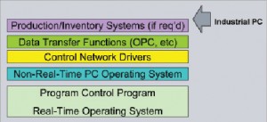
A hybrid system may be the best solution for modular machine control. A hybrid system consists of:
• An industrial PC to mitigate standard PC reliability issues;
• A real-time OS to guarantee performance;
• A deterministic controller program running at the real-time OS level to provide the I/O and controller data exchange functionality and can act as the coordinator;
• A non-real-time OS that can support data exchange functionality, enterprise functionality, HMI/SCADA functionality and custom code;
• Has an internal communication path between the non-real-time and real-time functions.

Figure 2 shows the structure of a hybrid system.
Industry organizations, such as IADC, can provide huge benefits for industries that need modular machine control. They can define standards for each machine type. The standards should encompass data formats for machine commands, operating status, setup information and production data. Data security and performance standards should also be defined for the machine-machine communications. Finally, the standards should be enforced.
One thing that could reap huge rewards for the industry would be a machine certification program where adherence to the standards is certified by the industry organization. This ensures that all machine types will be interoperable. This methodology is used to certify the operation of PROFINET and PROFIBUS devices, which seldom have interoperability issues once they have been certified.
This article is based on a presentation at the IADC Advanced Rig Technology Conference & Exhibition, 18 August 2010, Houston, Texas.
Wayne Cantrell is principal system engineer for Siemens Industry.


