LWD sonic sensor technology can complement wireline CBL evaluation to validate top of cement
Gulf of Mexico case studies show how logging-while-drilling sonic sensors can be used to provide confirmation of TOC, save rig time
By Franck Michel, Ben Robbins, Steven Kizziar and Nasreddine Laroussi, Halliburton; Michael Ehiwario, Rivers Fike, Jonathan Garrett, George A. Fuller and Glenn Donovan, Shell Offshore

Evaluation of cement placement is an important part of the majority of deepwater wells. Cement placement confirmation is a critical step following the cementing operation. More than one technique can be used to provide information about the top of cement (TOC) and the depth interval of a good bond between the formation and the casing. Determining the length of annular cement coverage, which is an indication of correct cement placement, is useful knowledge before drilling and/or completion operations can proceed.
The requirement for additional and improved cement evaluation techniques is greater than ever before. A variety of methods can be used to evaluate cement placement. The routine approach after a casing or liner cement job uses a job chart to calculate lift pressure and actual vs predicted system pressure. These data enable an estimate of cement height in the annulus to be made, but they do not confirm the TOC. These methods also vary in accuracy and difficulty, depending on well conditions.
Common TOC evaluation methods in specific wellbore casing/liner sections typically require running a temperature survey or cement bond log (CBL) sensors/systems on a wireline. These operations use the rig’s critical path time for each wireline run, which can add risk or difficulties, depending on the well trajectory. In addition, cement bond evaluation for large-diameter casing can be technically challenging because it can reach the upper threshold measurement limitations for conventional wireline-conveyed CBL tools.
Many operators now use logging-while-drilling (LWD) sonic sensors for compressional and shear data acquisition in open-hole environments. Using the same sonic systems and with minimal additional rig time, logging data acquired through the casing/liner strings while running a drilling or clean-out assembly can be evaluated to confirm the TOC.
This article demonstrates how LWD sonic technology can provide confirmation of the TOC, saving considerable rig time compared with performing a dedicated wireline evaluation run or potentially unnecessary cement squeeze operations.
Three Gulf of Mexico (GOM) case studies are also presented. Based on various challenges, through correct data analysis, TOC evaluation best practices are implemented to optimize the LWD acoustic data acquisition inside the casing/liner. New data examination techniques that can be applied to different scenarios are also reviewed. Further, information is provided about the LWD cased-hole logging techniques, analysis and results of the data application.
Logging Service and Data Acquisition Optimization
An acoustic logging tool consists of at least one transmitter and several series of receivers, referred to as receiver arrays. A sound wave is fired from the transmitter, which propagates and is detected by the receivers. Based on the known distance between the source and the receivers aligned with the source, the time the waves arrive at each receiver facilitates the calculation of the wave’s velocity.
In an open-hole environment, the acoustic wave propagation occurs through the mud and along the wellbore wall. In a cased-hole environment, the wave propagation only passes the casing if the latter is bonded to the cement. In cases where the bond extends to the formation, wave propagation travels down the formation.
The sonic tool starts data acquisition as a field-programmed time delay expires, regardless of the rig operation.
A sonic acquisition firing is followed by the storage, in the dedicated tool memory, of the full waveforms used for post-processing, downhole computation of acoustic semblance(s) and real-time data transmission to surface of high-coherence arrivals from the downhole computed semblance(s).
The acquisition flexibility of such tools, off the critical path of rig operations, enables data logging inside casing for cement evaluation purposes. Care is taken to configure the tool appropriately to acquire data while inside the cased hole. The tripping speed (i.e., logging speed), if it needs to be restricted, should be agreed upon while in the planning phase, specifically when logging close to the target zone(s). The aim is to log depth intervals of the theoretical and expected TOC with 100 ft or greater overlap while tripping in the hole and possibly while tripping out of the hole. It might be necessary to perform an analysis of both trip-in and trip-out data acquisitions if environments have changed between the two passes, such as if wellbore fluid density changed during the trip.
Other operational considerations include acoustic firing mode(s) selection at specific frequencies and data sampling rates for both real-time and memory. Most recent LWD acoustic tools are capable of firing multiple acoustic modes (i.e., monopole, dipole, quadrupole) during the same sampling period, which allows for independent data sets from each firing during the same pass — for instance, two monopole firings at different frequencies. The prejob stage also needs to emphasize the importance of good depth tracking for such acquisition during the tripping of the bottomhole assembly (BHA).
Data Analysis Methodologies
The waveforms acquired by the receiver closest to the transmitter for each receivers array are used for the TOC data analysis. Acoustic waveforms acquired inside casing respond as follows (Market et al. 2004):
• If a good cement bond exists, the casing signal will be weak and the formation signal strong.
• If a poor cement bond exists, the ringing of the casing will be strong and the formation signal weaker.
Figure 1 presents an LWD acoustic data acquisition behind a single string of casing. When reviewing the waveforms acquired by the closest receiver to the transmitter for one of the receivers array, a clear contrast can be identified at approximately X1,400 ft. The two intervals above and below that depth illustrate the two conditions mentioned.
• Track 1, measured depth (MD) markings in feet and LWD memory sonic data density tick marks for the raw waveforms acquired from the logging pass presented.
• Track 2, raw waveforms presented as a waveform trace.
• Track 3, raw waveforms presented as a variable density log (VDL) trace.
• Track 4, processed acoustic semblance presented as a VDL trace.
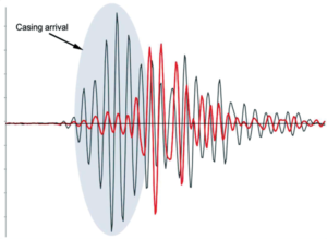
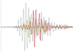
In Figure 2, two waveforms are presented from the two intervals mentioned. The casing arrival can be observed on the waveform for the shallower depth non-bonded interval, with a well-pronounced ringing effect of the casing being recognized. In comparison, the waveform from the deeper depth well-bonded interval shows evidence of the formation arrival with a non-existent or attenuated casing arrival. Representative sample waveforms from cased-hole logging when compared with a representative sample waveform from an open hole (Figure 3) show the formation compressional signal observed on the waveform from the cased-hole well-bonded interval.

In common practice, there is no automatic method for determining the TOC. The raw acoustic waveforms are analyzed and reviewed to identify where their character changes.
A common TOC analysis using LWD acoustic recorded data relies on different techniques that complement each other to provide more confidence in the analysis results:
1. Review of the raw waveforms recorded by the closest receiver to the transmitter for a high-frequency monopole firing to identify intervals where the casing was or was not ringing;
2. From an unfiltered processed acoustic semblance for a high-frequency monopole firing data set, determine if formation compressional arrival is visible. This would indicate that the casing is bonded to the cement and the cement is bonded to the formation;
3. From an unfiltered semblance for a high-frequency monopole firing data set, process the casing arrival based on a specific narrow slowness window (suggested 53 to 62 µsec/ft) to obtain a “casing energy” response to make an assessment from such response, which is considered the closest indicator comparable to a qualitative cement amplitude measurement;
4. Compare multiple passes (from trip-in and trip-out, based on a change in environments) for repeatability.
Based on actual design features of an LWD acoustic tool, the data transmission of downhole computed peaks from predefined real-time slowness windows is possible. The real-time slowness window can be pre-defined to cover the anticipated formation compressional slowness range, as well as the casing arrival. The peaks transmitted allow for making the following assessments:
• If all of the peaks transmitted are for the casing arrival, there is strong evidence that the casing is ringing (no bonding).
• If all the peaks transmitted are for the formation compressional arrival, there is strong evidence that the casing is bonded to the formation.
During the prelogging stage, it is important to consider configuring the real-time slowness windows for a TOC application. Having available open-hole data or offset well data for the formation compressional slowness response expected across the cased-hole section where the TOC is to be identified will greatly assist in the configuration planning.
The data analysis can be more credible with a higher confidence level if the depth interval logged covers a clear contrast between free pipe and good bond, which can be interpreted from the data acquired.
Figure 4 presents a suggested LWD acoustic TOC analysis plot format. This example shows a nonbonded zone transitioning to a well-bonded zone behind a single string of casing at X9,600 ft.
• Track 1, MD markings in feet.
• Track 2, open-hole gamma ray response as a scalar trace and casing mode energy presented as a qualitative bond response with shading illustrating the bond magnitude.
• Track 3, raw waveforms presented as a waveform trace.
• Track 4, raw waveforms presented as a VDL trace.
• Track 5, processed acoustic semblance presented as a VDL trace and interpreted casing mode as a scalar trace.
Case Studies
Case study 1
One of the major challenges while drilling wells in the young formations of the deepwater GOM is zonal isolation of the intermediate casing strings. Often during cementing operations, mud losses are encountered in the weaker formation, leaving uncertainty about the placement of the cement at the conclusion of the job. Operators analyze the cementing lift pressures from the job chart and calculate the TOC behind the casing, then drill out the casing shoe and perform a formation integrity test or leakoff test to verify the integrity of the isolation.
In many instances, LWD sonic tools are included in the deepening runs, and a battery-powered tool allows recorded waveform data to be acquired while the drilling BHA is tripping in the hole to drill out ahead. In these cases of uncertain cement placement, the raw waveform data are often capable of determining a TOC by using a macro-log presentation to locate the contrast of free ringing casing and the bonded casing to the formation. Without any impact or effort other than ensuring the sonic tool is on and sampling, the TOC is often identified and noted for possible future needs.
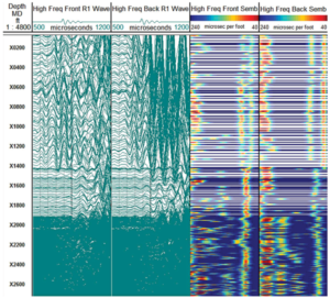
Figure 5 demonstrates a typical macro-log for a case study involving a 13 5/8-in. intermediate casing job. Mud losses while running the casing, cementing and displacing plug of 55 bbl, 349 bbl and 1,423 bbl, respectively, were recorded. With a planned lift pressure of 700 psi, the final differential pressure was 650 psi, putting the calculated TOC at X1,430 ft.
Tracks 1 and 2 of the macro-log show the raw waveform data of the high-frequency monopole firing nearest to the transmitter, and Tracks 3 and 4 are the processed semblances using the waveforms from all of the receivers. The LWD sonic sensor was in the drilling BHA downloaded for open-hole logging for real-time pore pressure guidance and seismic tie-in and recording waveforms with a 12-second sample rate. The gaps in the semblance tracks represent the time between samples at regular tripping speeds. The change in the waveforms representing the TOC is clearly noticeable around X1,420 ft, but depth resolution is limited by sample period and tripping speed. These results supported the calculations made from the final lift curve and place emphasis for further opportunities to evaluate TOCs without conventional wireline operations.
This case study is typical of LWD acoustic open-hole logging, where measurements acquired inside the casing while tripping are used for a TOC analysis.
Case Study 2
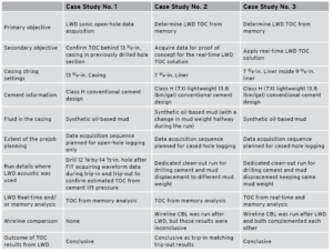
On this well, the drilling fluid was displaced during a dedicated clean-out run soon after the cement job was performed. The purpose of the clean-out run was to drill the cement inside the casing and perform a complete drilling fluid displacement. The mud weight difference before and after mud displacement allowed the LWD acoustic logging while trip-in and while trip-out to occur while the casing was pressurized differently. A cased-hole wireline logging run for cement evaluation was also performed after the clean-out run. During the wireline run, it was not possible to perform a pressurized pass for micro-annulus confirmation.
Following the cementing of the 7 5/8-in. liner, the client expected cement integrity issues and planned to perform a squeeze job. A clean-out run for drilling through the cement inside the 7 5/8-in. liner occurred, followed by wireline CBL run on tractor logging to confirm the TOC.
Other facts were: Liner was reamed to total depth (TD); returns could not be established during the cement pumping operations; the final differential (150 psi) during cementing was less than planned (180 psi); and based on cement lift pressure, the cement column was expected to be less than planned by about 150 ft.
To address the challenges, the LWD sonic tool was used to acquire acoustic waveforms inside the liner during the clean-out run. This was to assist with identifying and confirming the TOC from wireline CBL. The LWD tool was also optimized to operate by firing two monopole high-frequency modes and to acquire data in memory at a fast sample rate for sufficient data density without slowing tripping operations.
With the acquisition of quality LWD acoustic data, identification of a TOC inside the 7 5/8-in. liner was possible at X9,650 ft MD. The TOC was confirmed based on four data sets acquired from two firing modes, and from trip-in and trip-out data acquisitions. Both waveform analysis and casing arrival interpretation methods complemented each other in providing the analysis results.
Wireline CBL was not conclusive, indicating no cement was present behind the liner, possibly resulting from a micro-annulus. Analysis of the LWD acoustic data helped identify a micro-annulus and the TOC. As a result, it was decided not to perform a squeeze job. This allowed normal drilling operations to resume and the remaining hole section for the well to be drilled.
Case Study 3
The main objective in this ultra-deepwater GOM operation was to confirm the TOC of the 7 5/8-in. inner pipe inside the 9 5/8-in. liner. An LWD real-time application for determining the TOC was required to allow quick operational decisions and was followed by wireline segmented bond tool (SBT) logging. During the cementing of the 7 5/8-in. pipe, the primary cement job had full returns with an estimated TOC at X7,501 ft.
Challenges were determining TOC of the inner pipe; real-time cement evaluation during LWD logging; and quick decisions on the cased-hole wireline logging run.
Solutions were proof of concept using available LWD acoustic open-hole tool, and optimizing LWD data acquisition to meet the objectives and allow for normal tripping speed with limited impact on the critical path.
An LWD sonic log was run five days after the cement job during the clean-out trip. The LWD sonic run yielded a clear indication of cement below and above the liner overlap, with TOC at approximately X7,500 ft. A wireline SBT log was run after the 3,800-psi casing test and provided a more ambiguous indication of cement in the liner overlap, but TOC was still observed at approximately X7,490 ft.
The difference in results between LWD and wireline SBT might be attributable to a micro-annulus through the overlap interval.
SBT analysis showed that bonding was consistent with the designed cement compressive strength and no channels from X8,258 ft to the log first reading at X8,412 ft. The interval from the 9 5/8-in. casing shoe at X8,134 to X8,258 ft shows the presence of a channel in the cement.
The log response alternates between a free pipe reading and that of poor bonding from X7,490 to X8,134 ft. All of the logged footage above X7,490 ft reads free pipe. Of note is that the interval in the 7 5/8- by 9 5/8- in. annulus from X7,490 to X8,134 ft was so close to the free pipe response that a TOC call was difficult to make with certainty.
While TOC from wireline SBT was not as clear, TOC from LWD was more easily discerned. Both LWD and wireline cement evaluation results complemented each other greatly, and analysis of the wireline results on their own would have been difficult.
Conclusions
LWD TOC determination can provide significant value by complementing analysis of the wireline results. When possible, correlation with a gamma ray tracer response (based on add-on of radioactive material in the cement at a controlled volume before the cement is pumped) can assist with the cement bond analysis from LWD acoustic. Lessons learned included:
• Real-time LWD sonic reduced the rig time required for these TOC applications and decreased risks associated with wireline logging.
• The LWD logging service, along with results from the case studies, demonstrate that during the different stages of such services, accountability is important for critical decision-making inputs, such as the following:
■ Eliminating a planned cement squeeze operation;
■ Removing a dedicated wireline cement evaluation logging service;
■ Validating the cement integrity behind pipe before drilling a new hole section.
• Wireline CBL evaluation is still industry-preferred, with the solutions discussed being strong viable alternatives for complementing the evaluation. DC
Reference: Market, J., Schmitt, D.P., and Deady, R. 2004. LWD Sonic Logging in Cased Holes. Presented at the SPWLA 45th Annual Logging Symposium, Noordwijk, The Netherlands, 6–9 June. SPWLA-2004-U.

