GOM deepwater well puts dual-gradient drilling on the map

By Katherine Scott, associate editor
IADC defines dual-gradient drilling (DGD) as a variation of managed pressure drilling that uses “two or more pressure gradients within selected sections to manage the well pressure profile.” Although it’s not exactly new technology – it was introduced as early as 1975 – after years of research and trial, DGD is now on the verge of changing the face of deepwater drilling, with a successful application on the ultra-deepwater exploration well C-1 in the Gulf of Mexico (GOM) in May to July 2012. During the project, PETRONAS and AGR successfully applied what the companies believe to be the world’s first controlled annular mud-level type DGD system in the 17 ½-in. and 12 ¼-in. sections. No losses were seen, and the hole was in good condition with no indication of fill or drag through the 47 days the system was in operation.
“People initially think DGD is complex, but nothing has really changed. Flow in still equals flow out. The only thing that changes is that the riser level is no longer at surface, but you still measure bottomhole pressure (BHP) with pressure while drilling (PWD) in exactly the same way. Once you realize that, and it’s all the same that you’re used to, people then become a lot more comfortable with this type of drilling,” Paul Ashley, exploration well delivery manager – Atlantic region for PETRONAS, said.

When a previous drilling attempt on the same field did not reach its objective due to an inability to maintain a water-based mud system light enough to sustain circulation, the operator decided it needed a system that would allow for dynamic management of the equivalent circulating density (ECD). It was decided that conventional rotating control device management systems were not suitable because the drilling fluid was not light enough to manage the ECD via backpressure. Further, with a rotating control device, the riser top would have to be modified. “As we were in the GOM with the possibility of having to drill in the hurricane season, any modification to the top system of the riser would change the weather window the rig can operate in,” Robert Ziegler, head of deepwater drilling technology for PETRONAS, said.

Over a six-month period, PETRONAS and AGR jointly designed the EC-Drill DGD system for drilling post-BOP sections. The system uses a subsea pump installed on a modified riser joint to manipulate the height of the drilling fluid in the riser annulus. By manipulating the fluid level in the riser, it is possible to alter the hydrostatic pressure seen by the wellbore and control the ECD while drilling. The system also makes it possible to evaluate pore pressure/fracture gradient, early kick and loss indication and reduce formation damage.

DGD can be applied under several scenarios, including where fractured carbonates have high potential losses and in narrow pressure windows when BHP needs to be controlled, Roar Malt, drilling advisor for AGR, said. “Also, it’s possible to use DGD in deepwater with the sole purpose of reducing the number of casing strings. In some areas, it’s necessary to use five or more casing strings to reach total depth, but using DGD with high mud weights reduces the number of casing strings. That’s a huge benefit.”
Compared with a typical backpressure-based MPD system, the EC-Drill reduces the actual height of a heavier fluid column, allowing for a significantly flatter mud pressure gradient much closer to nature. This leads to a significantly lower pressure at the weak shoe, while maintaining the required pressure to control moveable formations.
The system consists of surface and subsea equipment, such as an office and tool container; control container; winch with umbilical; hose handling platform; control and monitoring system; subsea pump module; mud return line; and modified riser joint.
“There aren’t really any other commercially available dual-gradient systems on the market. One of the enablers for this technology is for the drilling contractors to work very closely with the operators who want to use it,” Mr Ashley said.

Although the AGR crew was familiar with the main components of the EC-Drill system, the application was new and had important changes compared with the riserless mud recovery system that the company predominately used previously. Therefore, before operations commenced, a one-day course describing the system and its application was held for the entire crew, followed by a one-week internal course. During the weeklong course, participants were presented with a module that explained the basics of drilling, formation pressures and volume control and how these aspects are affected by the EC-Drill system. Then, participants received a module that described the equipment, the installation and deployment procedures. Finally, the control system was explained in detail and the course was completed with a test. Operators were set up as a normal crew in order to make the test realistic.
AGR also built an in-house, onshore wellsite information transfer specification (WITS) simulator that connected to the EC-Drill control system program and helped operators practice operational procedures. It enabled the trainer to test trainees on operating the system’s equipment in various operational scenarios, such as normal drilling ahead, tripping, kick/loss incidents, etc. “We had a one-day simulator training where we drilled the entire well, so we knew the system and how to use it in the operation,” Kjell-Rune Toftevåg, senior control system manager for AGR, said.
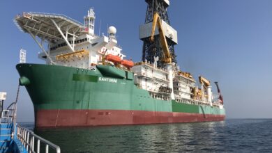
The C-1 well was spudded on 25 May 2012 in 2,260 meters of water from Saipem’s Scarabeo 9, a dynamically positioned sixth-generation semisubmersible. A 24-in. hole was drilled to 3,161 meters TVD before the riser and BOP were run. The EC-Drill system was then run together with the riser.
DGD operations commenced on 21 June; a 17 ½-in. and a 12 ¼-in. section were drilled. The formation in both sections was generally carbonates, with potential for severe or total losses. DGD was applied to prevent losses from occurring, and dynamic circulation pressure effects were eliminated. The DGD topside system was rigged up offline, and when running the riser, the DGD pump was launched and attached to the riser for the last 400 meters of riser running.

There were variations in flow, but the EC-Drill system was capable of maintaining a riser level of 150 to 200 meters with 1,650-gal/min flow in the 17 ½-in. section, which was above expectations, and ROP was demonstrated to increase when decreasing BHP.
In a technique called managed pressure cementing, the EC-Drill system was also used while cementing the 13 3/8-in. casing to control BHP. In deepwater drilling where there’s a narrow margin, inevitable pressure makes it difficult to cement the casing or liner in place, potentially resulting in losses, Saiful Anuar Sabri, onsite drilling engineer for PETRONAS, said. “This system lowers the pressure level such that you can circulate prior to the cement job, and when the heavy cement goes through the shoe and starts rising in the annulus, you can drop the level further to eliminate that pressure you get during cementing. It’s the difference between a good cement job and one with losses. We applied the EC-Drill during cementing, and it was very effective.”
One lesson learned was that because of the abnormally high pressure differential at the casing-running tool caused by the reduced riser level, a much higher set-down weight than normal was required to set the seal assembly. This was initially not taken into account, and first attempts therefore failed. After applying sufficient weight, the seal assembly was successfully set and tested.

“If there is ever a seventh generation of deepwater rigs, such a system should be standard equipment because it has benefits in any deepwater drilling scenario,” Mr Ziegler concluded. “Industry has understood that DGD is a game changer for deepwater drilling, and there have been a whole series of field trials with complex systems, but the system that we have now developed with AGR is a simple system that can also be easily retrofitted on an existing rig.”
The C-1 well was drilled using conventional methods of influx detection (Schlumberger/GeoServices Early Kick Detection System, PVT readings of the active system, and gas/salinity levels in return flow), and because the EC-Drill pump is installed below the slip joint, the return flow is not affected by vessel motion. In addition, the power consumption of the subsea pump module’s centrifugal disk pumps was monitored since it’s directly related to the volume of the mud pumped. Therefore, variations of the power consumption serve as a kick/loss detection instrument with steady-state flow-in. This kick/loss detection capability is within a single barrel, considered a major breakthrough on a floating rig.
There were zero incidents relating to influxes into the wellbore while the EC-Drill system was in use, and the mud weight was always maintained high enough to ensure that loss of the mud pumps would not lead to the wellbore becoming underbalanced.
This article is based on a presentation at the 2013 IADC/SPE Managed Pressure Drilling and Underbalanced Operations Conference & Exhibition in San Antonio, Texas, 17–18 April 2013, by Robert Ziegler, Paul Ashley, Saiful Anuar Sabri, M. Ramdan Idris, PETRONAS; Roar Fredrik Malt, Roger Stave, Kjell Rune Toftevåg, AGR EDS-ORS.