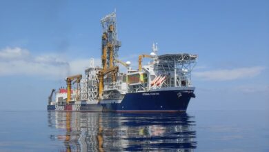
COSL Offshore to drill for Equinor at Statfjord in North Sea

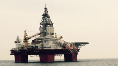
Equinor has awarded COSL Offshore Management a contract to drill four wells on Statfjord Øst with the COSLPromoter semisubmersible from the spring of 2023. In addition, the rig has options for drilling five wells for Statfjord satellites afterwards.
The contract value is calculated at around $56 million for the fixed part of the contract, which has an estimated duration of 220 days.
The value includes drilling and completion services, fuel, treatment of wastewater, handling of cuttings and upgrading of the rig by installing an automatic drilling control system. Additional services include running of casing, remote-operated vehicle (ROV), mobilization and demobilization, calculated at around $4 million.
After the preliminarily planned work program has been completed, the intention is to extend the cooperation by continuing options. Prior to the planned work program, options for any other tasks have been agreed. After drilling for Equinor on the Troll field from April 2013 to April 2021, the COSLPromoter is currently in hot lay-up at the CCB base outside Bergen.
“With this contract Equinor shows continued demand for smaller rigs on the Norwegian Continental Shelf as long as they are competitive and fit for the required drilling operations. The rig will be anchored at Statfjord Øst, helping maintain a low carbon emission level. We are pleased that COSL assumes responsibility for the fuel consumption, and they are working on several technologies and measures to reduce their emissions. This work will be important to us going forward,” said Mette Ottøy, Chief Procurement Officer (CPO) at Equinor.
The rig will have a key role in Equinor’s commitment to extending the life of late-life fields, where safety, efficiency, new ways of working and low emissions are central to maintaining profitable operation.
“We are pleased to continue the good cooperation with this rig, which has provided safe and efficient deliveries to us for eight years on the Troll field. We are also looking forward to continuing our effort on late-life fields together with an experienced player, and we have high expectations to COSL helping us reach our FLX ambitions,” said Erik G. Kirkemo, Senior VP of Drilling & Well Operations at Equinor.