Collaboration delivers fully integrated subsea completion in Norway
Case study: Methodical planning, installation process enable operator’s first subsea completion in Norwegian North Sea
By Martin Oliphant, Weatherford
Collaboration between the operator and service company has helped ensure the successful and safe installation of the first fully integrated subsea completion in the Norwegian North Sea.
Subsea completions, in which the wellhead and significant control architecture are located on the sea floor, have been successfully used to reduce development costs. However, as wells are drilled and completed in deeper waters and HPHT reservoirs, new solutions are required.
A first in Norway
An operator in the Norwegian sector of the North Sea needed such a solution for the subsea installation of two wells at a water depth of approximately 127 meters (417 ft). This represented the first subsea completion for the operator in Norway, which faces some of the most stringent offshore regulations in the world. Norway’s Petroleum Safety Authority (PSA) places priority on ensuring that project partners work in a coherent and cooperative manner to reduce accident risks. In addition, the PSA mandates that appropriate safety barriers are implemented and maintained in an integrated and consistent manner to ensure long-term well integrity.
Weatherford was selected to design, build and install the subsea completion for the two satellite oil wells with 9 5/8-in. main bore casing, which were to be tied back to a nearby wellhead platform. The subsea wells would contain connection points for a production pipeline and control cable with pipes for hydraulic and chemical delivery, signal cables, electrical power cables and gas lift.
An optimal completion
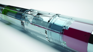
The company’s Optimum cased-hole completion system was selected for this application. The system implements various completions technologies that meet specific needs and are selected in a modular manner. A customized completions solution is created by mixing and matching these technologies based on the requirements of a given well.
Selecting the proper subsea completion system, with both the capacity for the required cable and gas-lift systems and the ability to provide the necessary level of well control, began with a review of reservoir conditions, expected production profiles and planned operating life of the wells. With this information supplied by the operator, Weatherford completions engineers conducted upfront engineering, project planning and product development work.
This included subjecting candidate components to a comprehensive testing program to evaluate their suitability under the expected downhole conditions of temperature, pressure, load and strain. Results of this screening process were shared with the client through a Weatherford engineer permanently installed at the client’s offices in Trondheim, Norway. This engineer not only updated the client’s engineers on the testing and development program, but also relayed feedback and new information to the completions team to update or improve the testing and design process.
Based on early reservoir review and qualification testing, Weatherford and the operator arrived at a fully integrated subsea completion system for both wells, with essentially the same architecture.
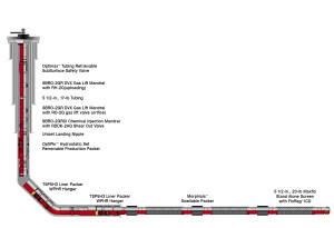
The main components of the lower completion consisted of:
• More than 100 5 ½-in., 20-lb metal mesh standalone screens with an inflow control device, designed to regulate flow into the screen and prevent formation sand from creating localized erosion – commonly known as a “hot spot” – on the screen.
• Swellable packers, designed to isolate different producing zones of the formation and prevent cross-flow between them in the event of a pressure differential.
• Liner packer hangers, which would take the weight of the tubing string and act as barriers between the reservoir and the casing.
The upper completion included:
• A 9 5/8 x 5 ½-in. OptiPkr hydrostatic set removable production packer to provide a seal between the outside of the production tubing and the inside of the casing.
• A chemical injection mandrel with shear-out valve, which would deliver production chemicals, such as scale and paraffin inhibitors, during production. The majority of North Sea wells are completed with chemical lines in the event that chemical injection is needed sometime during the well’s producing life, which is more cost effective than performing an intervention to install these lines at a later date.
• Two 5 ½-in. gas-lift mandrels, the lower with an orifice valve and the upper with an unloading valve. Gas-lift simulations indicated that the wells would need artificial lift to maintain production rates within 12 to 18 months.
• An Optimax tubing retrievable subsurface safety valve (SSV), which would provide positive shutoff protection in the event of a catastrophic loss of well control. Per PSA, all wells operating in the Norwegian North Sea are required to have an SSV in place to contain well-control events and prevent the release of reservoir fluids to the environment.
With the proposed subsea completions system decided, a quality control plan was developed with and approved by the operator, which documented the quality assurance requirements for the manufacture, inspection and testing of all cased-hole completions equipment for the wells. The plan also detailed every sequence of activities, from the development of the manufacturing process to the delivery of equipment to the wellsite. The plan included detailed descriptions of separate activities, including orders for vendor parts and equipment, in-house and subcontractor manufacturing processes, finished-goods quality control and final inspection, assembly instructions and quality control, and delivery procedures of all equipment to the rig site. The person responsible for approval of each activity was clearly identified, as were any reference documents and acceptance criteria. In addition, the document captured any operator quality-assurance and control requirements.
With this plan reviewed and approved by quality-assurance representatives from both Weatherford and the operator, the manufacturing process proceeded, with the majority of equipment built in Aberdeen and Houston. Prior to running any equipment downhole, all parties responsible for the deployment of the subsea completion system met to systematically review the steps required to safely and efficiently deliver each tool into the well. This process, referred to as a “well on paper,” was repeated several times over the course of five days to give the engineers a thorough understanding of each step and to be prepared with alternate processes to address installation setbacks that may arise.
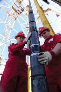
The installation plan for both wells was identical and began with a pre-job safety meeting with all personnel involved, with particular focus on handling of the completion assemblies. A blowout preventer (BOP) was then installed and tested to 250 bar with brine with a specific gravity (sg) of 1.03.
The lower completion, consisting of 102 joints of 5 ½-in. screens with swellable packers spaced between, was installed. The 9 5/8-in. main bore casing was then prepared for the upper completion by scraping and pressure testing to 250 bar with a 1.45-sg fluid.
From bottom to top, the procedure for the upper completion consisted of running in hole:
• The 5 ½-in. tubing handling equipment, spooling units and accessories.
• A 7-in. seal stem with indexing mule shoe and a 7-in. to 5 ½-in. crossover assembly to a measured depth of 3,090 meters.
• One 5 ½-in. tubing joint, followed by a bottom landing nipple.
• The OptiPkr production packer, including a top-landing nipple, followed by 5 ½-in. tubing joint.
• A downhole pressure-test gauge mandrel and the chemical injection mandrel. Separate pressure tests were conducted on the pressure-test gauge (7,500 psi for 10 min), the fitting between the mandrel’s injection valve and the control line (345 bar for 10 min) and the control line (100 bar for 10 min) prior to continuing with the installation.
• Gas-lift mandrel with orifice valve and gas-lift mandrel with unloading valve, with 5 ½-in., 17-lb 13 Cr tubing in between.
• More 5 ½-in., 17-lb 13Cr tubing according to tally, to ensure the SSV would be placed at the correct depth.
• The Optimax SSV, with splice subs above and below, followed by a pressure test of the SSV control line (690 bar for 10 min). The control line was then pressured up and maintained at 400 bar to keep the SSV open while running additional tubing in hole.
• Additional tubing until the tubing hanger depth was reached, followed by a bumper wire anchor sub.
A 10 ¾-in. by 5 ½-in. tubing hanger was then run in hole and landed, followed by additional pressure tests on the tubing hanger from above and the SSV. The production packer was set, and final pressure tests were conducted on the production tubing, packer and the chemical injection control line. An inflow test of the SSV and various pressure tests on the tubing hanger and valves set in different positions closed out the installation procedure.
Future applications
The upfront planning and collaboration with the operator, coupled with a methodical installation and pressure-testing program, helped ensure that both subsea completions were installed efficiently. The installations were completed two days ahead of the scheduled time.
The two wells were to be brought online in Q2 2013, and the successful installation of these initial subsea completions has prompted the operator to use this strategy for future wells in the field and in the greater North Sea.


