Saudi Aramco applies 4IR technologies to improve safety, well control readiness at rig site
Auto Well Space Out, Wireless Remote BOP Control and upgrades to BOP hydraulic hoses all aim to facilitate well shut-in, evacuation
By Michael Affleck, Aramco Overseas Company; Richard Pye, Bodong Li and Guodong (David) Zhan, Saudi Aramco
Despite the best efforts of everyone involved in drilling a well, accidents still occur, and some of them result in loss of life or permanent injury. To address this challenge, Saudi Aramco’s research teams in Aberdeen, UK, and Dhahran, Saudi Arabia, are working on three new technologies, enabled by Fourth Industrial Revolution (4IR) innovations, targeted at shutting in the well in a timely and safe manner in the event of an emerging well control situation.
Current state
What’s below the Earth’s surface is usually relatively unknown, even though efforts are made to predict pressure gradients, design casing programs from offset wells and engineer drilling fluids to drill the well safely.
Due to a variety of reasons, such as pockets of overpressured formation, an underestimation of the formation pressure or poor drilling mud management, formation fluids can be unintentionally introduced into the wellbore. Depending on the size of the influx, they can significantly reduce the effective bottomhole pressure as they make their way up the annulus.
As formation fluids (water, oil or gas) migrate up the wellbore, the incident worsens with time, and well unloading accelerates. Gas kicks can be extremely dangerous as the gas comes out of solution and expands rapidly due to the reducing pressure. It is always better to act early and decisively to contain a potentially out-of-control well. Thus, techniques and training, including regular practice drills at the rig site, currently focus almost entirely on early intervention. Drillers are required to check the well for undesirable flow and shut in using blowout preventers (BOPs).
Before closing BOP valves or rams, the driller must calculate that no obstruction lies across the valve being used. An obstruction will almost certainly prevent some BOP sections from securing the well. The most common tubular string obstruction is the tool joint. Pipe sections, including the connections, are typically 30- to 44-ft long, with the connections themselves approximately 12 to 18 in. in length. If necessary, an obstruction must be moved away from the valve to be actuated by changing the string vertical position using the main rig hoist or drawworks, or spacing out.
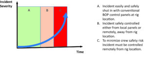
For reliability and security, drilling standards dictate that the monitoring and control of the BOP systems must occur through wired connections, at fixed locations on the drilling rig location. On a land rig, such locations typically include the rig floor, the BOP control unit (often under the rig) and at the toolpusher’s office. In the event of a developing well control incident, response time is key to how the event will turn out. A best-case scenario is one where the incident is spotted early, the well is shut in, and the influx is safely circulated out of the hole. However, all too often, situations are not spotted early. Figure 1 shows how the severity of an incident increases exponentially with time.
Depending on the situation and the equipment available at the rig site, it may be that the only safe method of assessing and initiating the corrective process is from a remote location. In Figure 1, this period is represented by column C.
Column B represents the period of uncertainty where there is often no single correct course of action. How much more effective would it be to have a procedure for rig evacuation during this period? In blowout situations, which invariably lead to rig fires, it is the personnel closest to the rig floor at the time who are usually severely or fatally injured.
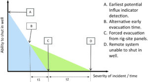
During period t1, with the knowledge that monitoring and control is still possible beyond evacuation, companies can instruct personnel to evacuate potentially hazardous zones earlier than may be the case today (point B vs point C). The time and/or severity escalation during periods t1 and t2 effectively becomes an increased safety window. Period t2 on the horizontal axis is defined as the time during which rig evacuation begins at point C, and the window of opportunity to shut in the well ends at point D, at which time the wireless system is unable to secure a well shut-in, possibly due to system elements failing through exposure to extreme heat or pressure (explosion).
There are two key stages to a successful manual shut-in:
- a. The well must be spaced out correctly
- b. The chosen annular or rams must close
There is one key stage to a successful remote shut-in.
- a. The rams must close
When developing new technology, the research teams sought to address these main challenges:
- 1. Reduce risk of an attempted shut-in with incorrectly spaced-out string in hole.
- 2. In the event of serious incident, allow (or mandate) the crew to evacuate to a safe distance from the rig site before functioning the final BOP element.
- 3. Ensure the equipment remains functional long enough to execute a remote shut-in command.
Auto Well Space Out
The Auto Well Space Out technology constantly monitors the position of tool joints above and below the rig floor level to calculate and inform the driller if the required BOP can be reliably functioned or if the drill string needs to be moved. In addition to being an advisory system, on some rigs, the BOP control system can be updated to prevent the operator functioning ram close. On other rig systems the hoisting system can be set to automatically adjust the drill string to space out when a tool joint proximity is calculated.
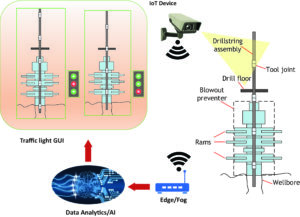
It works by using one or more high-definition cameras positioned at approximately 30 ft on the rig floor to observe the well center. The camera(s) have sufficient resolution to detect changes to the drill string position and properties, including drill pipe outside diameter (OD) as it is deployed into and out of the wellbore.
Image data from the camera(s) is fed to an Edge gateway processor, which combines the data with operator input parameters to calculate the relative position of the string when moving it into and out of the well. By continually tracking the positions of the larger OD sections (tool joints) and knowing the fixed positions of the BOP ram components (Figure 3), it is possible to dynamically calculate the positions of those tool joints or other larger components relative to BOP position. To ensure accuracy, it is important that the camera has visibility of at least one tool joint or major tubular OD change at all times.
In another application, the plan view position of the tubular string is monitored for centralization through the rotary table, which can be significant for some BOP ram functionality and in other drilling operations.
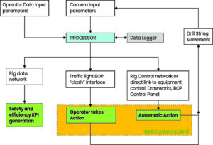
Figure 4 details the control loops associated with primary function processes. Data input comes from two sources: operator and camera image. The operator input is low-frequency data of the type that changes less than once per day on average, whilst the camera provides parameters that update at a frequency greater than 1 Hz. Both data sources feed into the Edge Gateway Processor unit. After processing and storage, data is output to multiple locations.
In the simplest application of the technology, a traffic light human-machine interface (HMI) allows the user operating the BOP panel to identify a potential problem that would prevent a reliable well seal. Such information allows the driller to proceed with immediately shutting in the BOP if “green,” or selecting an alternative BOP in the stack or moving the string to ensure there is no clash if “red.”
Wireless Remote BOP Control
The Wireless Remote BOP control system provides the rig crew an opportunity to evacuate earlier, increasing the potential to save lives. In blowout incidents that result in rig fires, the rig crew is often incapacitated from the start, which escalates the severity of the incident. After a certain point, no one is able to manually shut in the well because they are either trapped, injured or, unfortunately, dead.
A wireless remote shut-in has only one function – an emergency closure of the BOPs. The system is only hooked up to one set of rams. It is to be operated as a last resort when the situation has deteriorated to a point where it is the only option left.
With regulators reluctant to authorize the use of wireless communications in well control applications, the research teams sought a supplementary solution that could provide additional functionality without affecting or compromising existing systems and procedures.
To this end, an additional set of rams is added to the BOP stack, which will be actuated by the wireless controller. These are blind shear rams designed to sever the pipe and seal the wellbore; at this stage in the incident, space out may no longer be an option.
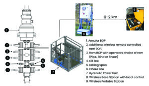
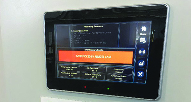
The system hardware is described in Figure 5. An additional set of rams (item 2) is added to the stack and connected to a dedicated hydraulic power unit (HPU) (item 7), which in turn is connected to a wireless base station with local controls (item 8). The base station is situated at the rig site and contains the PLC, HMI and radio telemetry device. The base station acts as a monitoring point for the HPU and controls and as a secondary control station. It allows the ram open function, operationally required for system testing and training. Additionally, the base station hosts a UPS and a user display showing key operating parameters, such as ram close pressure (trend), ram open pressure and accumulator pressure.
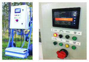
The BOP ram can be functioned from the base station or from a wireless portable control station (item 9). In addition to closing the ram, the wireless station provides status feedback and strength of the radio link. The portable unit is mounted in a carry case suitable for shock, vibration, sand and heat exposure. The device has an HMI to provide process status with instructions and feedback on use. Valve operation is a multi-stage process to prevent accidental or unauthorized BOP activation. All switches and buttons have covers to reduce the chance of mis-operation.
The portable station has continuous backup power, with the ability to be charged either from a mains power supply or an electrical point in a vehicle. The light weight of the unit allows for flexibility in its use. At rig sites where H2S may be present, it would be advantageous to not house the unit in a fixed location, which may end up being downwind of a release. Instead, the unit can be located in a truck, which can be moved to a safe location upwind to operate.
Upgrades to BOP hydraulic hoses
The successful operation of the remote shutdown system (or the existing BOP operation) depends on having sufficient hydraulic pressure at the time it’s needed. It was concluded after an incident investigation from a blowout fire in 2018 in Oklahoma that the hydraulic hoses linking the accumulator unit to the BOPs had failed due to high temperatures before the BOPs were attempted to be closed. In attempting to function the BOPs, the toolpusher and companyman had put themselves in a dangerous situation for what was, ultimately, a futile endeavor.
Referring back to Figure 2, the point D at which the system is no longer operable in a rig fire due to failure of equipment can be just a few minutes. In order for this system to work as intended in a burning rig scenario and to buy the crew as much time as possible to shut in the well from a remote location, possible weak links need to be eliminated.
Prompted by the findings of the report, the research team looked at the existing specifications for the hoses (API 16D) and found them to require a survival time of 5 minutes at a temperature of 704°C. This spec was considered to be too conservative given that a hydrocarbon fire can reach 1100°C very quickly. The location of the hoses and likely fuel source during a well blowout means that a hose needs to be able to withstand the higher temperature and, if possible, for longer than 5 minutes. Evidence from independent third-party testing and from the incident report suggested that the current hose configuration would fail at the 5-minute mark or earlier in a hydrocarbon fire. At the current lower API specification temperature of 704°C, the hose easily exceeded the requirements.
The company tested a commercially available hose design from a global manufacturer to establish the benchmark performance at the two temperatures and a number of new designs incorporating a silica-based material. The new material was again commercially available and is currently used for protecting pipework from extreme fire and heat.
Testing was done under API 16D qualification conditions. In total, four new configurations were tested, and the best exceeded 15 minutes before failure. This tripled the requirements of the specification at 704°C at the new elevated temperature of 1100°C, and this should provide sufficient time for the rig crew to get to a remote wireless box and shut in the well. The research team also believes this time can be pushed out with further design tweaks to the hoses.
In conclusion
Ensuring a well can be shut in is of paramount importance to protect the rig and its crew. The three technology advances presented in this article improve the chances of a successful shut-in by tackling different aspects of the problem.
The Auto Well Space-Out removes guesswork and relieves pressure from the driller in stressful situations. Additional functionality can also apply safety features designed to prevent accidental closure of the wrong valve by tying into the rig system.
The Remote Wireless BOP Controller and the upgrades to the hydraulic hoses buy the crew extra time and allow them to leave the rig at an earlier juncture. Removing them from the rig will reduce the chances of serious injury whilst the ability to secure the well remains.
Although currently applied to land drilling, these technologies can be easily transferred to the offshore environment. DC


