Eco-friendly invert emulsion fluid retains wellbore stability
3-stage development approach taken to formulate fluid without organoclay, low-gravity solids or inorganic salt solution phase
By Shadaab Maghrabi, Vikrant Wagle and Dhanashree Kulkarni, Halliburton
Over the past decade, invert emulsion drilling fluids that are free of organoclay have become popular. Improved wellbore stability, high rate of penetration, fragile gels, reduction in downhole losses during drilling and increased tolerance to contamination are among the associated benefits.
However, in the absence of organoclay, it is difficult to obtain optimal rheology for low- to medium-density invert emulsion fluids (IEFs) formulated with mineral oils. For successful drilling, the IEF needs optimal rheology and should be resistant to barite sag. In organoclay-free IEFs, low-gravity solids (LGS) – clay-type materials and micronized calcium carbonate – are added that interact with the polymeric rheology modifiers (RMs) to improve its rheology. The addition of
LGS improves its yield point (YP) but increases the plastic viscosity (PV). A high PV may lead to high equivalent
circulating density; in addition, a high volume percentage of LGS results in low rates of penetration.
Research on IEFs has concentrated on developing additives and systems that minimize sag by controlling rheology.
However, this approach delivers high-viscosity fluids, thus high equivalent circulating density. Another approach to minimize sag uses weighting agents with fine particle size, because small particles tend to settle slowly in the fluid. However, this increases the particle-particle interactions, leading to high PV. Thus, it is desirable to develop sag
resistance without significantly increasing viscosity.
Additionally, although IEFs provide excellent wellbore stability, this is a feature provided by incorporating an aqueous solution of inorganic salt, such as calcium chloride. In water, calcium chloride dissociates into positively charged cations and negatively charged anions. These ions bind water molecules, which decreases the water activity of the aqueous salt solution. As the concentration of salt increases, water activity decreases further. While drilling through shale, the water activity of the IEF is maintained at a lower level than the water activity of the shale, creating an osmotic pressure that drives water flow from the shale to the IEF, thereby preventing shale hydration.
However, the use of inorganic salts to maintain water activity poses challenges with cuttings disposal. For farming purposes, even when the treated oil-based cuttings are

mixed with soil, this mix still exhibits
high electrical conductivity due to the presence of salts, rendering the mix unsuitable for agriculture. Since the inorganics are non-degradable, the cuttings can be treated to a point lower than toxic limits via dilution. However, this does not eliminate the problem. Thus, there is a need to replace the internal inorganic salt solution phase with an internal phase that is biodegradable.
To eliminate the problem associated with using excessive LGS and nonbiodegradable calcium chloride internal phase, a new organoclay-free, LGS-free and salt-free IEF has been developed that employs a novel organic RM, sag-control additive and a biodegradable hygroscopic internal phase (HL). The use of the RM and sag-control additive eliminates the use of excessive LGS to get optimal rheology, while the use of a biodegradable internal phase eliminates the problem of cuttings disposal.
This article presents the three-stage development of this LGS-free, salt-free IEF:
1. Formulation of an LGS-based organoclay-free IEF;
2. Formulation of an IEF that is free of LGS and organoclay; and
3. Formulation of an IEF that is free of LGS, salt and organoclay.
The IEF will be discussed in terms of fluid performance, shale stability, tolerance to contamination, tolerance to static aging, HPHT rheology, fragile gel measurements and environmental impact.
Methods and materials
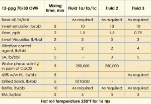
The IEFs were formulated with commercially available invert emulsifiers, lime, RMs, an HPHT filtration control agent and commonly used base oils. For this study, a naphthenic oil containing a high content of cyclic alkanes was used. The concentration of products was estimated with a proprietary numerical simulator.
The flow of experiments was:
1. The fluids were mixed in stainless steel mixing cups on a five-spindle multimixer at 11,500 rpm using a sine-wave impeller blade.
2. The fluids were aged in HPHT stainless steel cells in a hot rolling oven at 250°F for 16 hrs.
3. After hot rolling, the IEFs in the cells were inspected for oil separation and barite settling. Only the IEFs without oil separation or barite settling were considered for further study.
4. The IEFs were mixed on the multimixer for 5 min and placed in HPHT stainless steel cells, which were placed in an upright position and static aged in a mechanical convection oven with application of pressure as per API 13B-2.
5. After static aging, the cells were inspected for top oil separation.
6. The sag performance of the fluid was assessed by determining the sag factor. The specific gravity of the top (SGtop) and bottom (SGbottom) portion of the IEF in the aging cell were determined by drawing 10-ml aliquots and measuring their weights on an analytical balance.
7. The IEFs were mixed on the multimixer for 5 min. The rheology of the IEFs was then determined at 120°F on a 12-speed standard oilfield viscometer. The temperature of the fluid was controlled in an electrically heated thermo cup.
8. The fluid loss was determined on a 175-ml HPHT filter press cell.
The rheological and HPHT fluid loss tests were performed as per API 13B-2 recommendations, and the HPHT rheology was determined on a commercially available HPHT rheometer.
The sag factor for the static aged IEFs was calculated as (Equation 1):
Equation 1
SagFactor = SGbottom / SGbottom + SGtop
A sag factor greater than 0.53 implies that the fluid has potential to sag.
The rheology of the fluid was characterized in terms of PV, YP and low shear yield point (LSYP), where YP and PV are parameters from the Bingham Plastic rheology model. The YP is determined by extrapolating the model to a shear rate of zero, and it represents the stress required to move the fluid. Its value indicates the cuttings-carrying capacity of the IEF through the annulus – in other words, its hole-cleaning ability. A YP of 10-25 is considered good for drilling.
The PV represents the viscosity of a fluid when extrapolated to infinite shear rate; it indicates the type and concentration of the solids in the IEF, and a low PV is preferred.
PV and YP are calculated using 300-rpm and 600-rpm shear rate readings on a standard oilfield viscometer as given in Equations 2 and 3, respectively. The yield stress. or Tau0, is a parameter from the Herschel Buckley rheology model, which is the equivalent of the YP in the Bingham Plastic model. It is determined by fitting the Herschel Buckley model to the shear stress versus shear rate curve. The Tau0 is expressed in similar units as the YP indicates the susceptibility of the IEF to barite sag; a high Tau0 is proposed to deliver a sag-resistant IEF.
Equation 2
PV = (600 rpm reading) – (300 rpm reading)
Equation 3
YP = (300 rpm reading) – PV
Equation 4
LSYP = [2×(3 rpm reading)] – (6 rpm reading)
The gels formed in the IEF were characterized by the 10 sec/10 min gel strength, which represents the highest dial reading at 3 rpm on the viscometer, after keeping the IEF static for an interval of 10 sec/10 min. The gel strengths indicate suspension ability of the IEF for cut drill solids and barite particles when drilling stops.
Results and discussions
The 12-ppg IEFs were formulated at 70/30 oil/water ratio in the presence of polymeric rheology modifier, suspension agent and 60% w/w hygroscopic liquid sequentially to show the development of the final fluid. The mixing order, concentration and mixing time of the products are given in Table 1.
I. LGS-based organoclay-free IEF
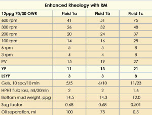
The 12-ppg IEF was formulated with 5-lb/bbl RM, drilled solids and 250K WPS CaCl2. The fluids were hot rolled at 250°F followed by static aging at the same temperature for 24 hrs. Three fluids were prepared with increasing concentrations of drilled solids. The mud properties are given in Table 2. The fluid with 0 lb/bbl drilled solids (Fluid 1a) was considered the base fluid. Fluids 1b and 1c contained 10 lb/bbl and 20 lb/bbl drilled solids, respectively.
Fluid 1a showed a YP of 11 and a LSYP of 3. After static aging, barite sag was observed at the bottom of the aging cell. Oil separation was 100 ml with a sag factor of 0.68.
The increase in PV, YP and LSYP for Fluid 1b was 26%, 18% and 0%, respectively, compared with the base fluid. Oil separation was 75 ml with a sag factor of 0.68. The increase in PV, YP and LSYP for Fluid 1c was 40%, 62% and 167%, respectively, compared with Fluid 1b. Static aging of this fluid at 250°F showed negligible oil separation with a sag factor of 0.5.
The HPHT fluid loss for all the fluids was less than 2 ml. The synergistic interaction of drilled solids and the RM increased the overall rheology of the IEF, with no barite sag, but adding LGS increased their PVs.
As the next step, a novel suspension agent was developed to eliminate the need for any type of LGS in the IEF.
II. LGS-free organoclay-free IEF
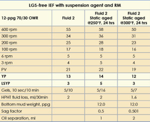
The 12-ppg IEF was formulated with a 3-lb/bbl suspension agent, 3-lb/bbl RM and 250K WPS CaCl2; mud properties are shown in Table 3 (Fluid 2). After static aging at 250°F for 24 hrs, the fluid gave a sag factor of 0.5 without top oil separation, and its rheology was higher, with a YP of 14 and a LSYP of 5. The gel strengths at 10 sec and 10 min were 5 and 16, respectively. This higher rheology resulted in greater emulsion stability and prevented barite from sagging.
The fluid was then subjected to static aging for 24 hours at 300°F. This gave a sag factor of 0.501 and top oil separation of 2 ml. The rheology of this IEF decreased slightly, with a YP of 12 and a LSYP of 3. The gel strength at 10 min, however, decreased to 7. This decrease in rheology did not result in top oil separation or barite sag.
The HPHT fluid loss obtained in all the fluids was less than 2 ml. Thus, the above fluid was formulated successfully in the absence of any LGS or organoclay.
As the next step, the internal phase of the IEF – 250K WPS CaCl2 – was to be replaced with an environmentally friendly, less toxic and more biodegradable alternative.
III. Salt-free, LGS-free, organoclay-free IEF
To develop a more environmentally friendly fluid, it was imperative to replace the existing CaCl2 internal phase with an alternative that had a better environmental profile. A hygroscopic liquid was chosen. The biodegradation and toxicity values for the HL were compared with CaCl2 and are shown in Table 4. The HL achieves 60% biodegradability in 10 days, compared with CaCl2, which is not biodegradable. The toxicity values for different organisms were higher for the CaCl2 internal phase than the HL.
The formulation for this 12-ppg salt-free, LGS-free, organoclay-free IEF along with the mixing order and mixing time are given in Table 1 (Fluid 3).
This IEF was formulated using a 60% w/w HL as the internal phase, 5-lb/bbl suspension agent, and a 3-lb/bbl RM. A 60% w/w HL concentration was chosen as a replacement for the 250Kppm CaCl2 solution because both show a similar water activity of 0.75.
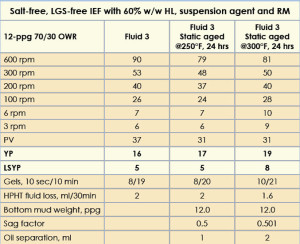
The fluids, after hot rolling at 250°F, were subjected to static aging at 250°F and 300°F for 24 hrs. It was observed that neither static aged fluids provided oil separation or barite settling. A sag factor of 0.5 was obtained when these fluids were tested. The rheological properties of the IEF are given in Table 5. The PV, YP, LSYP and fluid loss values of this IEF remained almost consistent throughout the static aging studies. Gel strengths at 10 sec and 10 min remained unchanged.
A. Performance of Salt-free, LGS-free, organoclay-free IEF under HPHT
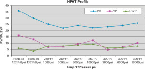
The performance of the 12-ppg salt-free, LGS-free and organoclay-free IEF was evaluated on a FANN 75 HPHT rheometer under HPHT conditions (Figure 1). The test pressures varied from 1,000 psi to 10,000 psi for a temperature range of 250°F to 300°F.
It was interesting to see that, under HPHT conditions, the LSYP was similar to YP and at times even higher. Since YP and LSYP are derived from different models, a low YP should not be construed as unsuitable for hole cleaning because, under the same conditions of temperature and pressure, the fluid had a sufficiently high LSYP to perform functions of hole cleaning and suspension. The PV of the fluid was low and almost constant under HPHT.
B. Contamination study
The IEF was then subjected to a contamination study where the protocol was:
1. Hot roll the IEF at 250°F for 16 hrs.
2. Measure the HPHT fluid loss and the rheology.
3. Mix the IEF with the contaminants for 5 min.
4. Hot roll the IEF at 250°F for 4 hrs.
5. Measure the HPHT fluid loss and the rheology.
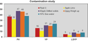
The contaminants used in the study were 40-lb/bbl artificial drilled solids, 10% seawater, a 2-ppg weight up with barite and 5-lb/bbl lime. The contamination testing results are presented in Figure 2.
• 5-lb/bbl lime: An overall decrease in rheological properties was observed after contaminating the fluid with 5-lb/bbl lime. The decrease in PV, YP and LSYP were 13%, 31% and 40%, respectively. However, these lower values can be treated easily with the RM and suspension agent to restore the fluids close to their original values.
For all the other contaminants, an increase in rheological properties were observed:
• Contaminating the fluid with 40-lb/bbl drilled solids provided an increase of 27%, 31% and 60% in PV, YP and LSYP, respectively.
• Weighting up the fluid with 2 ppg showed an increase of 24%, 25% and 20% in PV, YP and LSYP, respectively.
• The IEF contaminated with 10% seawater exhibited an increase of 3%, 50% and 60% in PV, YP and LSYP, respectively.
For all the contaminants, the HPHT fluid loss at 250°F was minimal at approximately 2 ml.
C. Fragile gel character
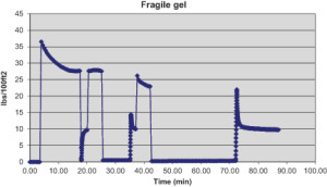
A “fragile” gel is easily disrupted or thinned and liquefies or becomes less gel-like and more liquid-like under stress. These gels are easily disrupted with a pressure wave or a compression wave during drilling, helping to prevent induced fractures that initiate fluid loss to the formation, especially due to surge and swab pressures. These fragile gels require lower surface pressures to break the gels, thereby eliminating the need to modify fluid rheology before running casing.
Measurements to determine fragile gel values were performed for the IEF. Steps in this experiment on the Brookfield viscometer were:
1. The fluid is stirred at 100 rpm to break any gel structure formed.
2. The gel peaks are measured at a shear rate of ½ rpm (viscosity is recorded once per second) after 10-sec, 10-min and 30-min static intervals.
3. Following the gel peaks, the fluid viscosity is measured at the same shear rate before stirring again at 100 rpm to break up the gel.
The viscosity-versus-time profiles for the fluid are shown in Figure 3. A gel peak of greater than 5 viscosity units after a 30-min interval is usually taken as the presence of fragile gels. The height of the gel peak is proportional to the amount of gel formed – the higher the peak, the more gel buildup. In Figure 3, after the 30-min gel peak (about 10 viscosity units), the viscosity curves fall rapidly with application of shear rate of ½ rpm, and then viscosity curve levels off. This indicates less resistance of the fluid to the stress and lower pressure required to move the fluid. It can be concluded that the IEF demonstrated fragile gel character.
D. Shale Stability Studies
A fundamental concern while drilling is the prevention of shale erosion. The shale-erosion test is used to measure the dispersive effect that a mud will have on a specific type of shale. Typically, 30 gm of oven-dried shale cuttings, sized between US#5 and US#10, are hot rolled with the drilling fluid at 150°F for 16 hrs. These shale cuttings are then screened through US#10 and then washed, dried and weighed to obtain the percent erosion of the shale. The initial moisture content is taken into account when calculating percent erosion (Equation 5):
Equation 5
% Shale Erosion =
[100 – Weight of retained shale cuttings/Original weight of the cuttings] x 100
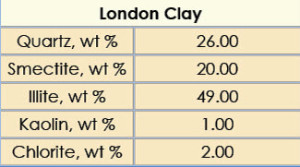
Shale-erosion studies were performed on London clay outcrop cuttings with the 12-ppg salt-free, LGS-free, organoclay-free IEF formulated with HL at 60% w/w internal phase concentrations. The XRD composition of the London clay outcrop cuttings is shown in Table 6.
The 12-ppg salt-free IEF formulated with 60% w/w HL concentration showed a shale erosion value of 0.9%. A low shale-erosion value of 0.9% shows that the salt-free IEF with 60% w/w HL internal phase concentration demonstrates good shale stability.
E. Environmental performance
Both the RM and suspension agent additives were subjected to biodegradability and eco-toxicity studies (Table 7). The RM and suspension agent were subjected to marine biodegradation assessment by the BODIS method, where biodegradation was recorded every week, up to 35 and 45 days, respectively.
The eco-toxicity studies were performed in the presence of marine juvenile fish Cyprinodon variegatus (a marine juvenile fish), Acartia tonsa (a marine copepod) and Skeletonema costatum (a marine algae) in seawater.
North Sea regulations require an offshore chemical to show an LC50 value greater than 10 mg/L and a biodegradability greater than 60% to be classified as suitable to use in North Sea. The RM and suspension agent additives are therefore North Sea-compliant because they not only show an LC50 value greater than 10 mg/L for each toxicity test but also show biodegradability in excess of 60%.
Conclusions
1. The polymeric RM imparted enhanced YP, LSYP and gel strengths to the clay-free IEFs without significantly affecting its PV.
2. Stable LGS-free IEFs were formulated with a novel suspension agent and a novel organic RM, with minimal oil separation and a sag factor close to 0.5.
3. A stable salt-free, LGS-free, organoclay-free IEF was prepared with an aqueous HL, a suspension agent and a polymeric RM. Static aging of this fluid at 300°F provided no oil separation and a sag factor close to 0.5. The formulated fluid showed excellent fluid loss control.
4. Salt-free, LGS-free IEF showed consistent YP and LSYP values at HPHT conditions across a range of temperatures and pressures.
5. The salt-free, LGS-free, organoclay-free IEF showed tolerance to contaminants. Deviations from the original properties can be restored with conventional thinners or RM and suspension agent.
6. The salt-free, LGS-free, organoclay-free IEF demonstrated fragile gels.
7. The salt-free, LGS-free, organoclay-free IEF demonstrated good shale stability.
8. Environmental studies showed that the IEF formulated with RM, suspension agent and HL can be used in regions with stringent environmental regulations.
This article is based on a presentation at the 2013 AADE National Technical Conference & Exhibition, Oklahoma City, Okla., 26-27 February.
Acknowledgements
The authors would like to thank the management of Halliburton for permission to present the work. We would also like to thank the Technical Paper Review Board of Halliburton for reviewing this manuscript.
References
1. Mowrey, C. and Cameron, C. 2006. “Achieving the Drilling Performance Benefits of a Clay-Free System in a Variety of Commonly-used Base Fluids.” AADE-06-DF-HO-07, AADE Drilling Fluids Technical Conference, Houston, April 11-12.
2. Kirsner, J. et al. 2004. “Method of formulating and using a drilling mud with fragile gels.” US patent 7278485.
3. Nicora, L.F. et al. 2001. “High-Density Invert-Emulsion System with Very Low Solids Content to Drill ERD and HPHT Wells.” SPE 65000, SPE International Symposium on Oilfield Chemistry, Houston, February 13-16.
4. Beck, F.E. et al. 1995. “The Effect of Rheology on Rate of Penetration.” SPE/lADC 29368, SPE/lADC Drilling Conference and Exhibition, Amsterdam, February 28 – March 2.
5. Bern, P.A. Zamora, M. Slater, K.S. and Hearn, P.J. 1996. “The influence of Drilling Variables on Barite Sag”, SPE 36670, SPE Annual Technical Conference and Exhibition, Denver, Colorado, U.SA, 6-9 October.
6. Bern, P.A. et al. 1970. “Barite Sag: Measurement, Modeling, and Management” SPE 62051, IADC/SPE Asia Pacific Drilling
7. Chenevert, M.E.. Shale Control with Balanced-Activity Oil-Continuous Muds. SPE 2559-PA. JPT 22 (10): 1309–1316.
8. Whitfill, D.L. and Boyd, P.A. 1987. “Soil Farming of Oil Mud Drill Cuttings”. SPE 16099, SPE/IADC Drilling Conference, New Orleans, Louisiana, 15–18 March.
9. Bleckmann, C.A. et al. 1989. “Land Treatment of Oil-Based Drill Cuttings” SPE 18685, SPE/IADC Drilling Conference, New Orleans, Louisiana, 28 February–3 March.
10. Ivan, C., Young, S., Bloys, B.: “Drilling Fluids Waste Management in Terms of a Sustainable Environment” AADE-04-DF-HO-23, AADE National Drilling Conference, Houston, Texas, April 6-7, 2004.
11. Curtis, G.W. et al. 2001. “Can Synthetic-Based Muds Be Designed to Enhance Soil Quality?” AADE-01-NC-HO-11, AADE National Drilling Conference, Houston, Texas, 27–29 March.
12. Growcock, F.B., et al. 2002. “Designing Invert Drilling Fluids to Yield Environmentally Friendly Drill Cuttings” SPE 74474, IADC/SPE Drilling Conference, Dallas, Texas, 26–28 February.
13. Maxey, J. 2007. “Rheological Analysis of Static and Dynamic Sag in Drilling Fluids.” Annual Transactions of the Nordic Rheology Society Vol. 15.


