Remote directional drilling enhances shale well quality, efficiency
DART centers allow Shell to pool expertise, streamline decision making for North American shales
By Cesar Gongora, Omar Awan, Jose Mota, Shell Upstream Americas; Eric van Oort, The University of Texas at Austin
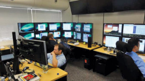
After a successful pilot application in the Haynesville Shale, Shell Upstream Americas is taking steps to conduct all of its directional drilling (DD), geosteering (GS) and measurement/logging while drilling (MWD/LWD) operations in the Americas and beyond from remote drilling centers.
The main drivers for the use of these centers are:
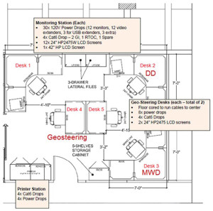
• More wells can be directionally drilled with the involvement of the most knowledgeable and experienced staff while new staff can be trained and developed effectively from a central location;
• Safety is improved by having fewer staff commuting back and forth to the rig site (i.e., reducing the number of driving-related accidents) and by reducing occupational exposure through having a smaller number of people “in harm’s way” at the rig site;
• Remote GS at a central facility allows for efficient communication between geologists and interpreters, with a single GS expert and a single geologist being able to handle a large number of GS operations at the same time, while greatly improving the speed of decision-making; and
• Staying within the shale target zone and reducing the number of GS corrections and doglegs while landing the horizontal section, resulting in noticeably improved wellbore quality. This yields immediate benefits in the ease of running production casing and will ultimately translate into higher hydrocarbon recovery.
Business case & justification
The phenomenal opportunities associated with unconventional shale oil and natural gas development in the Americas and elsewhere have brought important drilling, completion and production challenges to the forefront, including:
1. The need for improved production rates and ultimate reserves recovery to reduce unit cost ($/BOE);
2. The need for improved efficiency and associated reduction of “waste” in rig time and associated cost, again to reduce unit cost;
3. The need for improved safety, reducing occupational hazards and taking rig staff out of harm’s way;
4. The need for guaranteed competency among the rig staff and/or leveraging competent, experienced staff over a larger number of operations;
5. The need for effective high-volume manufacturing approaches for prospects that may require thousands to tens of thousands of development wells, where conventional staffing models for well construction break down; and
6. The need to address the “big crew change” in the oil and gas industry, i.e., the retirement of a whole generation of oilfield experts without proper backfill with younger resources.
All of these challenges and opportunities force us to consider new, more efficient ways of working, where a larger number of operations can be handled by a smaller group of people. This is now possible by leveraging IT and communications technology, software and hardware tools, automated systems, etc. These are the enablers behind the Drilling Automation and Remote Technology (DART) centers that are currently in operation in Shell’s unconventional shale business in the Americas. In those centers, DD, GS and MWD/LWD tasks are carried out remotely in dedicated facilities. The aim is to gain efficiencies by leveraging a small number of drilling experts over a larger number of operations while improving the quality, efficiency and safety of the well construction operation at the same time.
Historical development & time line
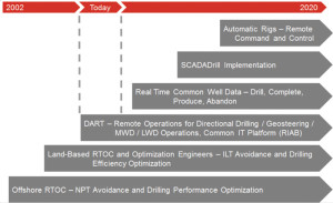
In a recent review of the history of drilling operations centers, two generations of such centers separated in time and function were distinguished (Booth 2009, 2011). Shell kicked off the second, more modern generation of real-time operations centers (RTOC) in 2002 with its facility in New Orleans, which was focused on offshore deepwater drilling optimization and nonproductive time prevention (Kaminski 2002, Ursem 2003). The success of this pilot facility led to worldwide adoption of such centers throughout the Shell group around 2005, with primary focus on deepwater “big cat” wells but later on also broadening to include critical land well operations (van Oort, 2005).
In more recent years – 2008 onward – effective ways have been developed to exploit real-time capabilities for fit-for-purpose drilling optimization on unconventional shale wells in North America (Billa, 2011). A range of value-adding tools and methods (MSE-based drilling optimization, automatic rig activity detection, dedicated root-cause failure analysis, etc) was used and placed in the hands of dedicated performance optimization engineers, who were seconded to field-operations teams to implement drilling improvements, minimize invisible lost time, etc. This approach contributed to the acceleration of drilling learning curves (van Oort, 2011).
When Shell embarked on the adoption of DART centers in 2010, the following prerequisites were in place:
• Extensive experience with the deployment of RTOC, its communication and optimization tools and methods, etc, as well as how to work these to add significant value to a large number of different drilling and completion operations;
• Ability to deploy reliable IT infrastructure that allowed for two-way communication between field-based drilling rigs and office-based staff;
• Field-based operations staff already being familiar with remote RTOC involvement and its benefits, without the traditional pushback that usually accompanies the introduction of any outside involvement; and
• Strong management support to test and develop new, value-adding ways of working that addressed the challenges and opportunities.
In early 2011, the first DART center commenced operations by leveraging the infrastructure of an existing land-based RTOC facility in Houston. In its early days, this DART center was dedicated to remote operations in the Haynesville Shale. Its initial capability consisted of being able to monitor up to three concurrent MWD and DD jobs on three rigs in the Haynesville from single MWD and DD stations. The change from the historical field-based DD approach to the new, optimized DART approach, where DD, MWD/LWD, GS and geology resources were co-located to allow for more effective integration and communication, ultimately translated into improved speed and quality of decision-making.
Wells were drilled remotely from the DART center through 2011, when nine rigs were deployed in the Haynesville drilling HPHT shale gas wells. As a glut in natural gas prices reduced the drilling program from nine rigs to one rig in March 2012, the Haynesville remote DD program was suspended because it became uneconomical to continue remote operations for only a single rig.
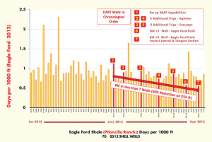
Operations were redirected and expanded toward shale oil and condensate wells in the Eagle Ford. Since June 2012, seven Eagle Ford wells have been directionally drilled remotely, with the last two wells considered best in class.
The evident merits of the remote DD approach have not gone unnoticed, and the Shell Group is planning an expansion of DART activities across all North America unconventional shale drilling operations, as well as an extension across the globe, starting with shale plays in China and Australia.
It is expected that the DART approach will gain further momentum to become the preferred way of directional drilling globally. Moreover, it is seen as a clear step up toward the goal of further automating and de-manning field operations to make them safer and more efficient.
DART objectives and approach
Shell’s DART objectives and approach are to:
• Drill multiple wells with single MWD/LWD, DD and GS resources working 24/7 from a remote facility;
• Carry out concurrent MWD/DD operations for three wells at the same time and concurrent GS operations for four wells at the same time;
• Continually improve the number of wells managed with fewer key positions:
• Carry out wellsite geology activities relating to MWD/LWD interpretation and GS in the remote center with a resident geologist;
• Improve journey management by having fewer staff commuting back and forth to the rig site, thereby reducing exposure to traffic incidents, and by reducing occupational exposure by having fewer people “in harm’s way” at the rig site;
• Bring previously outsourced GS operations in-house, facilitate the interaction between MWD/LWD, GS, DD and geology resources, and strongly reduce cycle time for wellbore trajectory corrections;
• Increase the consistency of build sections and horizontal laterals in shale zones by minimizing the number of required directional changes and reducing the dogleg severity associated with the changes that are required. This will not only benefit ease of casing-running operations by creating smoother wellbores but may ultimately yield higher initial production and ultimate reserves recovery by creating wellbores that remain in zone and can be used to stimulate reservoir rock more effectively;
• Improve efficiency and communication between field and office staff. DART centers can be used to hold effective meetings with rig staff while having all desired information readily available and can be used to hold morning operations calls while facilitating the availability and visualization of performance data;
• Provide a cost-effective solution for “Well Manufacturing Drilling,” also referred to as “Factory Drilling” (Gorgone, 2008, Ayllon, 2011), when large numbers of relatively low-cost wells need to be drilled efficiently and conventional ways of working and staffing become unsustainable (e.g., through the sheer lack of available resources);
• Become a first step in delivering the end-game strategy of progressive automation and rig de-manning, with the ability to conduct drilling and completion activities through remote command and control operations; and
• Controlling the IT infrastructure was an important objective from the start. Different data-aggregation, communication and visualization systems have been used, but continuity of use has often suffered from picking up and laying down rigs. Developing a customized solution for each rig is unfortunately not sustainable.
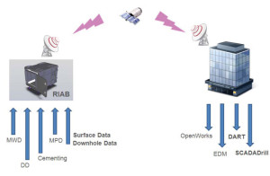
This is why the DART approach uses a standardized IT infrastructure solution named Rig-In-A-Box (RIAB) that could be deployed irrespective of the rigs and rig systems used.
DART solution delivery
Key elements of the DART solution delivery include the RIAB IT infrastructure and the way DART operations are carried out.
IT Infrastructure – RIAB
The DART centers allow for active communication with drilling rigs by conducting DD, MWD/LWD and GS operations remotely, with a single off-site operations team typically taking care of operations on multiple rigs at the same time. Through DART technology out on location, several sources of data are gathered and transmitted to the DART, thereby reducing the number of broadband pipes needed at the rig.
Proper execution of an information technology/information management project plan coupled with a structured maintenance and support (M&S) strategy are key factors for a successful DART implementation.
Three primary environments require careful attention in the IT space: (1) the rig site, (2) the office domain and (3) the end user.
RIAB is at the heart of the rig-site operation. It is a compact, robust, fully integrated and remotely managed piece of IT equipment that provides the necessary hardware and software to make DART function properly. The basic building blocks of RIAB can be divided into four main components:
1. A virtualized fault tolerant host server that can be referred to as the brains of the operation. It collects, aggregates, stores, processes and publishes real-time data in several basic and rich formats such as numerical, voice and video. It is capable of ingesting and publishing this data using several universal protocols.
2. A telecommunications package that provides secure and seamless bi-directional communication between the rig and the office domains.
3. A human machine interface to visualize the data at strategic locations on the rig.
4. Centralized monitoring and management of the equipment that provides real-time “health“ of the system in the event of a physical and/or network breach and/or failure. This allows for proactive support of the equipment and applications to minimize downtime.
A key benefit to the way RIAB is designed is that it is compact yet modular, both in terms of physical size and capability. It is designed to form-fit to the functionality and constraints of the rig and tailor its capabilities to the requirements of DART.
The telecommunications package in RIAB employs universal and secure tunneling protocols over any standard IP network (VSAT, microwave, mesh, 3G, etc) to allow data to pass transparently from the rig site to the office and vice versa. In other words, it creates a virtual corporate network on the rig that is accessible, given the appropriate rights and permissions, to any system or persons anchored in a corporate office setting, like a DART center.
The benefit of this standard approach is that it allows for quick and secure commissioning and decommissioning, making DART implementation easier when rig moves in and out of a field are frequent. Stable and resilient connections to the rig site are imperative to conduct DART operations; any interruption in communication could paralyze the workflows. Therefore, in the event of a communications failure, redundant IP networks, for example, microwave and satellite, can be cascaded, enabling a continuous flow of data without disruption.
Three main technologies allow for efficient remote MWD and DD operations: (1) graphical desktop sharing, (2) radio over IP (RoIP) and (3) video surveillance and analytics.
Graphical desktop sharing describes a software package that has the ability for a remote user using a local computer on a common IP network to visualize and interact with a remote computer. Three key features make for an effective graphical desktop sharing package for the rig-site environment:
1. Security. Because remote MWD provides the ability for a remote user to create and modify set points that can alter a drill string’s trajectory, several layers of security are required to enter a remote system on the rig from the DART center. Security levels include both the IP and application layers. Accounts and permissions for access are managed using standard protocols over a secure encrypted link.
2. Compression. Because some rigs are limited to high-latency and low-bandwidth links, the ability to compress desktop images is of significant importance. By selecting fit-for-purpose compression algorithms and color saturations, DART operators can effectively manage depth control and telemetry from any part of the world without rig-site intervention.
3. Portability. To account for many different MWD services using several telemetry systems and operating systems, it is imperative to select the graphical desktop sharing package that is easily ported to different operating systems and corporate security policies.
RoIP is a technology that was deployed to DART-enabled rigs to allow DART operators (MWD/LWD and DD) to be in seamless contact with key personnel on the rig, namely, the driller and company representative. Unlike voice over IP, RoIP is uni-directional and on-demand, making it an excellent solution for brief instructions to be sent over high-latency links. In our case, the system using existing radio systems already present on the rig make for quick integration. In addition, any user on the corporate network with a PC, Blackberry, Android or iOS device can be added to the channel in very short order; this allows for a robust collaboration suite that can also act as an emergency response system.
As discussed earlier, system reliability and uptime are important factors to fulfill many of the DART workflows, which is why the M&S aspects of DART should not be underestimated. From inception to agreement to operate, a specially trained team of IT professionals was involved and approved all major stage gates of the project. Having agreement from this group of individuals and a detailed list of responsibilities, accountabilities and service level agreements reinforces our reliance on M&S to insure all the hardware and software components of DART are properly supported and maintained. Moreover, aligning our M&S organization with our corporate DART long-term strategy at the very beginning allows for a healthy balance of innovation coupled with practical support procedures, thus minimizing surprises.
Geosteering
DART integrates GS with the geological expertise of the asset team to provide interpretations of the payzone geometry, which is then used for real-time well placement guidance. DART GS focal points work directly with operations geologists to obtain regional geologic information, such as formation thickness, expected dips, structural and stratigraphic targets, etc. Once this information is obtained, a framework for GS is built, which includes choosing the appropriate-type logs either from existing vertical pilot wells or by deriving them from nearby deviated wells. It is essential that the type log is as close as possible in proximity to the active well being drilled and on similar geologic structure to ensure fair and reasonable well geometry comparison.
When steering, the active well data is received from the MWD/LWD crew in the DART or from remote onsite locations, including data such as gamma ray, resistivity and density logs. This data is then correlated with the chosen type log to get a tie-in. The depth at which regionally identified stratigraphic markers are crossed is important for landing projections while the curve is being built. This information is shared with the geologist and drilling engineers to determine if adjustments by the directional driller will be necessary to keep the well landed on target depth or within accepted vertical tolerance of it.
Once the well is landed, it is important to keep the well within the tolerance of the target zone. This is done by taking updated MWD/LWD data and surveys and, using the GS correlation effort, proceed with an interpretation of the subsurface and its stratigraphic and structural changes. This gives information about the apparent dip value of the formation, its direction and how these are changing within the lateral. The best interpretation is shared and discussed with the geologist, who may wish to instigate well path inclination or azimuth adjustments when projections show certain target thresholds being breached. These thresholds, or tolerances, would have previously been discussed with the geologist, the drilling engineer and directional driller to avoid excessive corrections and unnecessary doglegs, which may pose problems when running production casing.
This process continues throughout while drilling to total depth, with scheduled daily reports, status updates and phone calls as advised on an a pre-agreed call point list. A final report is presented at the end of the well as a steering record, allowing for later research by the geologist and engineers for subsequent wells (e.g., on the same pad or at nearby well locations).
Directional Drilling
Remote DD requires drillers at the rig site to carry out slide operations under the remote guidance of the directional drillers, with the latter still remaining 100% in charge of the operation. A staged approach was used to teach the drillers how to run the directional equipment and to understand the overall goals.
First, the directional drillers started by standing next to the driller and giving him/her verbal instructions. While doing this, they explained why certain decisions and changes (about setting toolface, adjusting for reactive torque, etc) were made. Most of the drillers quickly became familiar with the decision-making process.
During the second step, the drillers started making a few changes on their own when needed during a slide. At this point, they started to understand what was actually happening with the directional assembly and its interaction with the rock formation downhole and required progressively less direct supervision for simple directional scenarios.
The third step was taking the directional drillers out of the field altogether and directing the drillers over radio using the RoIP technology. This transition was easy once the drillers understood what the directional drillers were trying to accomplish and how they should react to changes during a slide. Soon, there were drillers who are able to execute slides in the easier sections of the well with little help from the DART.
Note that a team of roaming directional drillers was kept in the field to assist whenever necessary during more complicated sliding operations, e.g., while drilling the curve. These field-based directional drillers are junior staff and are also directed from the DART.
It is the expectation that the need for these roaming resources will decrease once the skills and proficiency of the drillers is increased. Note that this approach still reduced the number of people on location: Three rigs typically deploy six directional drillers at any time (three days/three nights), whereas DART handles those same three rigs with two directional drillers (one day/one night) in the remote center with one to two roaming directional drillers in the field – a 33% to 50% reduction in staff.
During normal drilling conditions, the directional driller is using all the available data to instruct the drillers on location on how to drill in sliding and rotary mode parameters. Survey data are continuously compared against the directional plan, and decisions are made on the need to execute a slide. The directional driller will then communicate the requirements for tool face orientation and length of the slide to the driller, specifying required weight on bit (WOB), motor differential pressure, etc.
The driller will then proceed with drilling ahead while the directional driller will continuously watch the surface and downhole sensor data remotely, altering ROP, WOB and differential settings as needed to maximize drilling efficiency and accuracy. During the slides, the directional driller keeps a constant eye on the data to look for any settings that might be making the slide harder or slower than it could be.
Key challenges that had to be overcome included:
• Motivating the drillers to be a part of a remotely run operation and having them adjust to their new roles and responsibilities (e.g., operate the directional equipment);
• Identifying a radio/RoIP system that worked reliably and could be used in the noisy environment of the rig floor;
• Making the directional drillers comfortable with their remote, office-based location while still being fully in charge of the directional drilling operation. After an initial adjustment period of several weeks, they adjusted smoothly to their new role and work environment; and
• During the adjustment phase, the speed of slides executed by the drillers out on location was running at about 50% of the speed that the directional drillers out on location would achieve. The motor yields were also at a reduced level due to less steady tool faces during the slides. This is to be expected as part of the learning curve and continues to improve as drillers get more and more time and experience sliding.
Keys to success included:
• Leadership and communication skills of the directional driller. Even though the directional driller is located remotely, he/she should be fully in charge of the directional drilling operation, communicate effectively with all stakeholders, and command their respect and buy-in for decisions made. Not all directional drillers do well in a remote environment, but several individuals have performed beyond expectations;
• Good communication between all stakeholders (directional drillers, company representatives, drillers, etc) is key to success. In particular, the company representatives have been able to motivate the drillers to learn the remote directional drilling process and improve their proficiency, which is crucial to making the operation work; and
• Important tools that keep the directional drillers informed about everything that is happening at the rig at all times and allow them to make appropriate corrections include: (1) RoIP: the most important tool, as it constitutes the lifeline between drillers and directional drillers, allowing the directional drillers to talk directly with the people on location as if they were standing there with them; (2) VNC viewer: This allows the directional drillers to get a view of all the computers on location. For instance, they can watch tool face as they would see it on the rig floor. Moreover, they can see the MWD/LWD computers to diagnose problems and obtain new surveys, etc; (3) Real-time data communication: used to communicate and visualize real-time sensor data coming off surface and downhole sensors, including automatic driller settings.
Results
Haynesville Shale
In the Haynesville Shale, a total of 46 wells were drilled using the DART from 2011 to mid-2012, when rig activity dropped to levels where maintaining a dedicated Haynesville DART unit could no longer be sustained and operations were switched to Eagle Ford well construction.
The DART pilot work and subsequent wider deployment in the Haynesville, however, showed clear benefits. Until DART was deployed, GS work was outsourced, which meant that geological interpretations could take as much as seven to nine hours before communications for directional course corrections came back to the rig. With GS in the DART, the geologic interpretation became real time, and updates could be provided to the geologist, drilling engineer and directional driller within 30-45 minutes.
Overall, a 90% efficiency gain was achieved in the speed of interpretation and decision-making, which resulted in a noticeable improvement in wellbore quality. Drilling the production laterals, high levels of confidence were achieved on bit position with respect to formation stratigraphy and dip angles. The pattern of bit walk tendencies with respect to formation stratigraphy could be successfully delineated and used to proactively steer the wells while minimizing sliding time and maximizing rotating time.
Drilling performance was optimized by providing operations, engineering and geologic groups with more relevant real-time data for feedback and course corrections. Although ROP was some 18% slower on early wells drilled remotely compared with those drilled with the directional driller on location (primarily due to drillers adjusting to carrying out slides while taking guidance from remote directional drillers), tripping times improved by 21% and casing-running times by 9%. One of the main benefits achieved with the DART was consistency in drilling performance, largely due to having the same competent individuals involved in consecutive wells.
However, more importantly, the wells drilled remotely were able to stay 100% of the time in the target zone, something that proved impossible prior to DART use. None of the wells drilled at the Haynesville in the 13 months under DART control required geological sidetracks, whereas drilling conventionally required two to three sidetracks per quarter. The latter improvement provides a return on investment that justifies the upfront expense of putting the DART center(s) in place.
Eagle Ford Shale
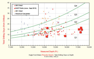
A steady improvement in drilling performance, characterized in days/1,000 ft, was observed, with an approximately 50% improvement in average drill rates observed over a period of seven wells drilled by the DART. Well 7 recorded one of the fastest lateral and tangent sections drilled by Shell in the Eagle Ford, at 0.44 days/1,000 ft (the record appears to have been broken on well 10 with 0.34 days/1,000 ft).
Six out of seven Eagle Ford wells drilled by the DART were top quartile when benchmarked against external competitors. The only well not in the top quartile was the first well drilled in the Eagle Ford using the DART approach, i.e., the well at the very start of the learning curve for the Eagle Ford. All build curves drilled using the DART were in the top 20% of Eagle Ford well history.
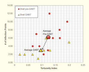
Using the DART, the two longest laterals (approximately 7,000-ft length) have been drilled to date, including the longest successful Ecoscope runs. Wellbore quality was also noticeably improved. The tortuosity index, a quantitative measure characterizing the tortuosity of the lateral dropped by 24% using the DART (from 0.125 to 0.095), whereas the average number of inflection points in the well dropped by 52% (from 6.2 to 3.0).
Discussion
Key Success Factors
A key factor contributing to the success of the DART approach was addressing people issues. DART introduction requires careful management of change to achieve buy-in from all stakeholders, even when there is strong senior management support backing the effort.
As with all real-time technologies, outside interference by remote resources may receive some pushback from field staff. Directional drillers may need time adjusting to their new role in a centralized facility, whereas drillers in the field need to be carefully trained in their new role as slide drillers. Especially in the early days of implementation, when additional time and resources are required to start the remote drilling effort and benefits are not yet evident, it is important to have a clear engagement and communication strategy with all stakeholders. This will allow the team to stay the course for a period long enough to demonstrate benefits (typically on the order of one year), and to clearly and widely communicate successes once they become available.
The DART lends itself well to help drive drilling improvements, with the drilling engineer, geologist and directional driller initiating optimization efforts, while the company representative supervises those in the field and prioritizes based on operations safety. On a more basic level, the DART has facilitated performance improvement simply by providing relevant, up-to-date information for structured daily morning calls and making sure that key personnel remain informed about upcoming targets.
DART operations have benefitted from setting achievable milestones (i.e., wells are broken down in smaller milestones instead of overall performance targets, making them more achievable), and recognizing performance accordingly. With all the rig data readily available, the DART is also in a unique position to identify performance limiters and to help address them.
Having highly experienced staff available in a central DART location allows for effective onboarding and training of new staff. The high-tech environment of the DART is particularly appealing to a younger generation and can be used effectively as a tool to attract them.
Future Outlook
From the early pilots in the Haynesville and the Eagle Ford, DART is being expanded to cover a wider range of activities and operations. Plans include facilities in Houston that will handle all Eagle Ford, Haynesville and Arrowhead operations. A drilling automation pilot program is being carried out with a dedicated rig in the Marcellus Shale. Because the automation team is located in Houston, its operations will be controlled out of Houston as well. A separate facility, under construction in Pittsburgh, will handle all other Marcellus activities. The Calgary RTOC will be remodeled to conduct DART operations for Canadian operations in Foothills, Deep Basin, Ground Birch (Montney Shale), Fox Creek, etc. In addition, there are plans to globalize the DART effort with centers in China and Australia.
Conclusions
Shell has implemented DART centers to address pressing challenges, particularly in unconventional shale well construction, associated with the need for improved safety, more efficient operations leveraging a smaller number of people across a larger number of operations, and obtaining high-quality wellbores. The DART approach brings together key resources, including DD, GS focal points, MWD/LWD interpreters and company geologists, allowing them to conduct their work effectively from remote locations. The speed of GS decision-making has been improved by 90%, with noticeable improvements in wellbore placement (staying in the target zone 100% of the time) and wellbore quality (reduction in wellbore tortuosity and the number of inflection points in the well).
These improvements have in turn improved casing-running operations and are expected to benefit the quality of the fracture stimulation and ultimately production rates and reserves recovery.
Meanwhile, DART has also been proven to be an enabler for best-in-class well delivery in the Eagle Ford and has been demonstrated to facilitate more consistency in drilling performance by having the same group of highly competent people involved in consecutive wells.
Given their solid return on investment, the reach of the DART centers is now expanded to cover all of Shell’s North American land-based well delivery operations and beyond. Moreover, the adoption of DART technology is seen as a step in the future implementation of supervisory control and data acquisition (SCADA) systems and automated drilling rigs.
Acknowledgements: Many people contributed to this paper. We would like to especially thank Don Sitton, RJ Mendoza, Christopher Klug, Edward N. Perry, Cory U. Osaze, Kyle J. Patterson, Sean Huggins-Chan, Matt R. Scheiner, Haroon Farooq, Mike Behrns, Justin Sappington, Randy Henderson and James Griffith for all their help, input and support. We also would like to thank Shell Upstream Americas for permission to publish this paper.
References:
Ayllon, R., and Hansen, R.: Factory Drilling Boosts ROP with Automation, Drilling Contractor, Nov/Dec 2011.
Billa, R., Mota, J., Schneider, B. and Weissman, M.: Drilling Performance Improvement in the Haynesville Shale, SPE 139842, 2011 SPE/IADC Drilling Conference, Amsterdam, 1-3 March 2011.
Booth, J.E.: Drilling Operations Centers: A History of Functionality and Organizational Purpose – The First Generation,” SPE 123225, SPE Digital Energy Conference and Exhibition, 7-8 April 2009, Houston.
Booth, J.E.: Real-Time Drilling Operations Centers: A History of Functionality and Organizational Purpose – The Second Generation,” SPE 126017, SPE Drilling & Completions, Vol 26, No. 2, p. 295-302.
Gorgone, I., Gomez, J., and Uddenberg, G.: “Remote Operations, The Future of Drilling: Directional Drilling Remote Control,” SPE 112599, IADC/SPE Drilling Conference, 4-6 March 2008, Orlando, Florida.
Kaminski, D.H., Pellerin, N.M., Williams, J.H.: A New Data Integration and Work Process System for Providing Online Real-Time Drilling Collaboration, SPE 78343, 13th European Petroleum Conference, Aberdeen, 29-31 October 2002.
Ursem, L.J., Williams, J.H., Pellerin, N.M., Kaminski, D.H.: Real Time Operations Centers: The People Aspects of Drilling Decision Making, SPE/IADC 79893, SPE/IADC Drilling Conference, Amsterdam, 19-21 Feb. 2003.
van Oort, E., Rosso, R., Cabello-Montero, J.: “Evolution of Real Time Operations Monitoring: from Concept to Global Implementation,” SPE ATCE 97059, SPE Annual Technical Conference and Exhibition, Dallas, 9-12 October 2005.
van Oort, E., Griffith, J, Schneider, B: “How to Accelerate Drilling Learning Curves,” SPE 140333, 2011 SPE/IADC Drilling Conference, Amsterdam, 1-3 March 2011.



Very good article.
How do you calculate tortuosity index? I know there are several methods and I’m trying to find one that will fit our trajectories, but I have no luck so far.
Thank you
Mihai