Onshore MPD system enables lower mud weights for challenging wells
Automated system incorporating rig pump diverter yields improvements in South Texas, Haynesville wells
By J. Montilva, J. Mota, R. Billa, Shell Exploration & Production Company
In the development of onshore gas fields, Shell has encountered margins in which the difference between dynamic equivalent circulating density (ECD) and static bottomhole pressure (BHP) is the difference between lost circulation and influx. The limits imposed by those conflicting conditions create narrow mud weight windows.
The reasons for the tight pore pressure and fracture gradient windows in these vertical and horizontal onshore high-pressure, high-temperature (HPHT) tight gas environments vary. Some are old fields challenged by depletion. In the case of South Texas, the main problem is losses in the production hole due to depletion.
The pressure in different zones is often difficult to predict due to complex geology, further complicated by years of commingled production without knowing what each zone has contributed. In some new shale plays, such as the Haynesville, slim-hole well plans are used, which have problems with low kick tolerance design and unexpected kicks through fractured intervals.
These pose unique well control challenges to minimize nonproductive time. In all of these wells, there is the high cost associated with losing mud and/or constantly changing mud weights to prevent losses or influxes.
To mitigate these potential problems, Shell has recognized the use of managed pressure drilling (MPD), which enables the use of the lowest possible mud weight to drill these challenging wells. By lowering the mud weight and manipulating the annular pressure during drilling, the risk of mud losses and/or quick sudden transitions into overpressured zones is reduced. There are some direct benefits of drilling with lower mud weight, such as higher rate of penetration (ROP), lower stand pipe pressures and lower circulating temperatures. In addition, there are lower ECD and higher pump rates that improve the hole cleaning.
Field trials using a fully automated MPD solution were performed by Shell in South Texas and North Louisiana Haynesville from late 2010 to mid-2011. This article describes implementation of a fully automated MPD, small rig footprint system. It incorporates a rig pump diverter (RPD) for smooth transitions from circulating to non-circulating downhole during connection while maintaining continuous rig pump circulation.
In this article, results will be presented that show how drilling with lower mud weights impacted well performance. Additionally, a comparison of vertical and horizontal HPHT wells that were drilled conventionally and wells drilled using MPD show the effects of drilling with lower mud weights on ROP, downhole circulating temperature, ECD, stand pipe pressure and pump rate.
Background
Shell has operated gas fields in South Texas for more than 50 years. These 10,000-ft to 16,000-ft HPHT wells normally have initial shut-in tubing pressures approaching 10,000 psi when virgin sands are completed. Most wells have multiple low permeability pay sands, which require hydraulic fracture treatments to produce economically. Severe pressure depletion intermingled with high-pressure sands is often encountered. For years, casing and liner drilling with statically underbalance (SUB) mud was used to reduce losses. This worked fine in tight reservoirs because you could take advantage of the low permeability and the solubility of gas in oil-based mud to drill with the ECD profile without taking significant flow during connections.
However, this does not work in higher-permeability rock that would experience flow and pressure build-up while making connections. As the desire to drill with even lower mud weights due to increasing depletion occurred, Shell turned to automated MPD to drill more permeable reservoirs with SUB mud without influx.
In 2008, Shell began drilling in the North Louisiana Haynesville, which lies between 12,000-ft true vertical depth (TVD) to 15,000-ft TVD. As the play moves south, it is deeper and becomes considerably hotter. The southern Haynesville formation yields bottomhole circulating temperatures that exceed 360°F during landing and drilling the long horizontal sections. The bottomhole pressure can also exceed 11,000 psi.
Underbalanced Drilling with Casing
The underbalanced drilling with casing approach was first applied to a slim-hole reentry program that began in 1995. These wellbores were sidetracked out of existing 5-in. or 5 1/2-in. casing, and a new string of 2 7/8-in. casing was run and cemented. By 2000, remaining reentry candidates were difficult to drill because of the high ECDs that caused lost circulation and well control problems.
Drilling with casing while underbalanced was applied to resolve these problems. The low permeability of the Vicksburg sands allowed operations with a higher underbalance than would be possible in most other applications.
The learnings from the reentry program were transferred to the drilling of new wells. Drilling new wells with casing while underbalanced enabled the casing program sizes to be reduced, eliminated liners and reduced cost, resulting in savings of approximately 30% to 50%.
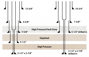
A comparison between a conventional well plan in an offset well and a drilling with casing underbalanced well plan is shown in Figure 1. A liner was eliminated by drilling in the 5 1/2-in. liner and the 3 1/2-in.-by-2 7/8-in. production casing. The intervals were drilled conventionally halfway through the shallower formations, stopping above the problematic zones to allow for open-hole logs.
After running logs, the problematic zones were drilled in. A constant 20-ft to 30-ft flare was observed while drilling the deeper high-pressure sands. The conventional well plan was typically drilled in 58 days. By drilling with casing underbalanced, that was reduced to 28 days on the first well. After that, drilling with casing using SUB mud became normal practice for South Texas wells.
Early MPD Systems
Automated MPD was chosen to extend the application of casing drilling from the typical Vicksburg fields to the more permeable Frio reservoirs in the McAllen-Pharr field. Compared with other nearby fields in the Vicksburg formations, those in the Frio have substantially higher permeability.
A limiting factor in the McAllen-Pharr field is the ease with which losses occur in many of the reservoir sands due to depletion (lower minimum horizontal stress). The resulting narrow pressure profile and the inaccurate pore pressure predictions had complicated Shell’s early drilling efforts with excessive lost circulation and well control events.
The use of liner drilling was limited in the field because of the high level of uncertainty about the pressures and permeabilities that would be encountered. Early on it was seen that the permeability of some reservoir sands was high enough to allow the gas to flow during connections when the mud is statically underbalanced. That limited the amount by which the mud weight could be reduced and the effectiveness of liner drilling.
To extend the benefits of drilling with casing, Shell sought a different way to avoid losses in the shallow depleted sands while drilling with the higher ECD needed to avoid influx in the deeper permeable reservoirs. The company had already decided to use MPD to manage similar problems in mature offshore fields, so it became a matter of adapting the technology to onshore conditions.
The automated MPD system that Shell was using in the deepwater Gulf of Mexico was adapted for onshore operations. It included a choke manifold, a backpressure pump and a Coriolis flow meter. A high-pressure rotating control device was used to provide the drill pipe seal.
After drilling the first wells, Shell started looking for ways to optimize the system. The focus was on ways to reduce the size and weight of the manifold to make it easier to handle, transport and rig-up. An important modification to the original MPD system was to eliminate the backpressure pump that was a main source of nonproductive time.
The new system consisted of a modular choke manifold and a Coriolis flow meter. A rig pump was used for additional flow as needed to boost the level of the trapped pressure. A principle benefit of the modular system’s small footprint and easy handling is the amount of time required to rig-up. In one well, the MPD crew rigged up the modular system in seven hours, which was 60% faster than the time it took to rig-up the system on the previous job and 85% faster than the average two days it took to rig-up the first full MPD system used on earlier McAllen-Pharr wells.
This MPD system was used during conventional drilling and drilling with casing operations. The typical plan for the 6 1/2-in. production hole was to drill with drill pipe the first part from the 7 5/8-in. casing shoe (about 8,700-ft MD) down to about 10,500-ft MD, and then drill in the casing in the second part to total depth (about 11,200-ft MD).
The primary objective in the first part of the 6 1/2-in. section was to drill through the depleted sections below the shoe, minimizing the mud weight. Accomplishing this objective allowed significant savings by eliminating the need for a 5 ½-in. contingency liner. The objective for MPD in the second part was to minimize the ECD to avoid losses and manage the gas while drilling in the casing in the payzone, where the pore pressure was at least 1.5 ppg greater than the maximum already drilled.
The system was used to manage the ECD while drilling in the 3 ½-in. casing and hold constant BHP during connections. One of the rig pumps was hooked up to the kill line to help manage the BHP and preserve the trapped backpressure by injecting mud into the annulus during connections.
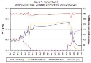
An example of a connection while drilling in the 3 ½-in. production casing is shown in Figure 2, which shows that the min/max window for ECD during this connection was 0.3 ppg (+/- 0.15 ppg). The slowly rising backpressure is due to the steady flow of gas from the well.
One final task after drilling in the 3 ½-in. production casing was to cement the casing in place. The trick was to avoid losing returns with the heavy weight cement. The cementing operation was modeled using a constant pump rate of 3 bbl/min for the entire job.
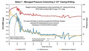
A controlled procedure using the MPD system was followed to regulate the backpressure for a fixed volume of fluid displaced into the drill pipe. That procedure carefully governed the effect that the 16.2 ppg cement had on the ECD as it filled the annulus. Careful regulation of the reduction in backpressure with the cement pump rate and close cooperation between the MPD and cementing crew resulted in successful cement jobs without losses.
Figure 3 shows the plot of the operational parameters during cementing operations for the 3 ½-in. drilled-in casing. The MPD system controlled the ECD between 16 ppg and 15.85 ppg by regulating the backpressure with the rate at which the cement was displaced in the drill pipe.
Another application of MPD in South Texas was to use the system during liner drilling operations. MPD was used to manage the ECD in the 8 ½-in. hole section while drilling in with a 7 5/8-in. liner assembly from 9,550 ft to 10,448 ft.
The objective was to drill the severely depleted formations situated below the 9 7/8-in. casing shoe without losses by using MPD to manage the ECD and using the drill-in liner to eliminate the need for heavy kill muds. Coarse calcium carbonate as background LCM and in sweeps was also used while drilling this interval.
Part of the challenge was in the nature of the pressure prediction, because both the fracture gradient and pressure prediction were estimates that would be verified by actual drilling conditions. In addition, the use of liner drilling did not allow the use of a pressure-while-drilling (PWD) tool; therefore, control was based on the hydraulics model integrated into the control system.
New MPD Approach
The previous MPD experiences were done using either a backpressure pump (BPP) or the rig pumps to help manage the BHP and preserve the trapped backpressure utilized during connections. A major issue with the BPP and rig pump is the ramping up and down between the rig pump and BPP or rig pump during connections. A fault in synchronization could result in backpressure spikes and lead to well control events, not to mention the big footprint of the BPP, which makes it difficult for mobilizing/rig-up and to operate.
In late 2010 and early 2011, before Shell sold its South Texas assets, the company conducted a successful field trial on five wells using the MPD concept with RPD technology for making connections.
The main feature of this new concept is that the RPD was designed to eliminate the need to shut down rig pumps during connections. By diverting the flow from the standpipe side to the annular side of the well, the automated choke can precisely keep BHP under control, eliminating borehole breathing effect during connections.
During the field trial period for all of the South Texas wells, Halliburton’s MPD package was used. It consisted of an automated choke skid, Coriolis meter skid, RPD manifold, data acquisition system (DAS) and the necessary pipe packages.
A total of five trial wells were identified as good candidates to apply the MPD concept with the RPD method for making a connection.
The first trial well was PFWU 59 in the Pharr field. The drilling objectives were considered to have been fully met. It was possible to drill the depleted sands with no losses and no well control situations. It was also possible to run 2 7/8-in. casing and cement it place using MPD technology. The biggest gain from this trial was the degree of comfort and receptiveness of the MPD/RPD technology by field personnel, which was a main driver to continue the trial.
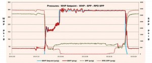
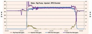
Figures 4 and 5 show the typical data output using the RPD to make a connection during MPD. Figure 4 tracks the set-point pressure calculated by the hydraulics mode. Figure 5 details the three flow rates tracked during each connection sequence: rig pump rate, RPD flow rate and choke flow rate. The software then uses these values to calculate the injection rate, which is the volume of fluid going down the hole. When the diversion begins, the injection rate decreases until the system is fully diverted and it is safe to make a connection.
The four candidates were Slick 225, Slick 227, Slick 228 and Slick 229. All these wells are in the Slick Ranch Field. Using the MPD concept allows for reduction in mud weights compared with conventional drilling and consequentially reduces the ECD. This reduces the risk of losses during drilling and improves ROP.
Using the MPD with RPD techniques significantly improved rate of penetration by up to 93% compared with offset wells, which were drilled conventionally. Overall, the average number of drilling days for the section was reduced from seven days per well using conventional drilling to 3.24 days using MPD system with RPD technique.
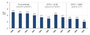
Figure 6 shows the overall effect on performance (days/1,000 ft) using conventional drilling, drilling with casing with SUB, and drilling with casing with MPD.
These techniques allowed the continued casing downsizing and the effect of improved time because of nonproductive time reduction and ROP optimization.
Simplified Underbalance Technique
In North Louisiana, horizontal wells targeting the Haynesville shale have been drilled conventionally using a simplified underbalanced technique. A rotating control device and the gas buster are used while drilling the curve through the Bossier and Haynesville shales because of the high risk of encountering gas kicks in these sections.
While drilling, the flow from the well is diverted through the rig choke line with one open choke to the gas buster, and the flow is returned to the shale shakers before reaching the estimated depth of a potential kick. With the flow routed through one fully open choke, the friction loss through the choke creates about 100 psi of surface backpressure (SBP). Any fluctuation in this pressure provides an additional indicator of increased flow from the well for kick detection.
If a gas kick enters the wellbore, the increased friction through the choke will increase the choke gauge pressure and will therefore indicate that a kick is in progress. If this pressure increase occurs, it will give indication of a kick prior to either the flow sensor on the outlet of the gas buster or the pit volume increase occurs.
When a kick is believed to be in progress, the driller will pick up off bottom to prepare to shut in the blowout preventers (BOP). The sequence of events should be essentially the same as a normal shut-in, except the BOP is closed before stopping the pump. The kick is then circulated out using the driller’s method.
Experience has indicated that kicks come from trapped gas in fractures and are limited in total volume. This procedure is designed to restrict and control the kick coming into the well rather than stopping it. The kick is “strung out” in the wellbore by maintaining flow and can be managed at surface within the fluid-handling ability of the surface equipment.
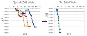
This approach also allows drilling the lateral section with a lower mud weight. As a result, the ROP increases and drilling time has been reduced significantly (Figure 7).
MPD in North Louisiana Haynesville
Based on the positive results obtained using underbalanced mitigating well control events, decreasing mud weight and increasing ROP, a field trial implementation of MPD using RPD during connections was undertaken in the North Louisiana Haynesville. The main objectives were to:
• Improve kick detection without compromising the rig choke (keeping it as a backup for well control);
• Cut the mud weight lower than the conventional historical values;
• Increase the ROP; and
• Reduce the time associated with handling well events in the production hole.
The main components of the automated MPD system used in this project were the same as those used in South Texas:
• Automated choke system;
• RPD;
• DAS;
• Rotating control device;
•Atmospheric mud gas separator; and
• Piping for both high- and low-pressure lines for use upstream and downstream of the MPD chokes.
There were two important modifications to improve the system. The first one was the inclusion of a high closing ratio valve to tie in the RPD upstream of the stand pipe. The benefit of this new valve is that the isolation of the stand pipe during the connection is done automatically from the drill floor. In the MPD system used in South Texas, this isolation was done closing the manual standpipe valve.
The second modification was to take the mud returns through the mud cross, installing a “T” with a second HCR valve. Depending on which HCR valve was close
/open, the mud returns could be circulated either through the MPD choke or the rig choke. The benefit of this modification is that, in a kick event, after the well is shut in, the kick could be circulated either through the rig choke or the MPD choke.
One advantage of the MPD system is that it allows continuous monitoring and evaluation of real-time drilling data via time- and depth-based plots. This enabled a 24-hr manned, trained crew to detect pressure abnormalities in the drill string by monitoring the stand pipe pressure and at the annular side by monitoring auto-choke behavior, presure-while-drilling data, drill gas, connection gas, trip gas and bottomhole temperature.
The MPD crew also monitored rig tank levels, losses and gains. Besides their continuous monitoring of drilling data, the MPD crew also set limits on what data should not exceed or go below and set alarms around those limits.
This early kick detection system is able to identify abnormal conditions with the use of Coriolis meters while drilling or circulating. It was developed to allow rapid response to any unpredicted change in the mud flow or pressure.
During the course of drilling the selected wells, the MPD crew was the first to notice drilling and pressure abnormalities and immediately bring it to the attention of Shell’s foreman and toolpusher. Two kicks were detected while drilling the curve in the other two MPD wells:
• The automated MPD system detected the first influx while drilling the curve at 13,210-ft MD in the second MPD well. The MPD supervisor reported the kick to the driller and Shell foreman. The well was shut in to 280-psi casing pressure. Choke was opened; pressure was bled off. Gas and bottoms up were circulated before resuming drilling. The well was checked for flow, but no flow was detected.
• The second kick was also detected when drilling the curve at 13,434-ft MD in the third MPD well. After an increase in flow was detected, the well was shut in, and a pit gain of 12 bbls was reported. The well was monitored for 30 min until pressures stabilized, with the recorded shut-in drill pipe pressure and shut-in casing pressure as 350 and 800 psi, respectively. The gas influx was circulated out through the rig choke, and a 5- to 15-ft flare was observed. After the influx was circulated out, the system was lined up and diverted back through the MPD system.
An oil-based drilling fluid was used to drill the production section, and mud weights ranged from 12.8 ppg to 15.0 ppg.
A brief summary of the mud weight strategy is below:
• Conventional well: The curve was drilled conventionally using a typical mud weight of 14.4 ppg, but it was necessary to increase it to 15 ppg while drilling the lateral. This change impacted the initial mud weight selected to be used in the first two MPD wells, and a higher initial mud weight was used instead.
• MPD well No 1: The curve was drilled conventionally using a mud weight of 14.5 ppg, and the mud weight was decreased to 14.0 ppg at the end of the curve. The lateral section was then drilled using the automated MPD system, decreasing the mud weight in stages to 13.8 ppg at about 15,000-ft MD. No surface backpressure was required while drilling, and an equivalent mud weight (EMW) of 14.4 ppg was maintained at the shoe during connections.
• MPD well No 2: The curve and the lateral section were drilled using the automated MPD system. Although lower mud weights were used in this well (14 ppg for the curve and 13.6–13.4 ppg for the lateral), no SBP was required during drilling either. The same EMW of 14.4 ppg at the casing shoe was maintained during connections.
• MPD well No 3: The automated MPD system was used in both the curve and lateral sections. A mud weight of 13.6 ppg was used to drill the curve, and it was decreased up to 12.8 ppg to drill the lateral section. Surface backpressure was required while drilling and during connections to maintain a constant BHP when drilling with 12.8 ppg static mud weight.
PWD is not commonly run because of factors such as additional cost and higher risk of having a “lost in hole” when drilling problematic zones. PWD was used during this field trial to measure if a constant BHP could be maintained during connections using the automated MPD system with RPD. Two different connections are discussed below: one during conventional drilling and the other while implementing MPD with the RPD.
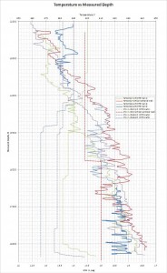
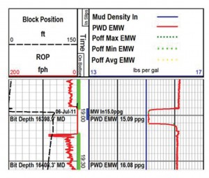
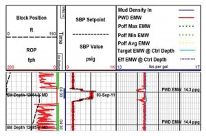
Figure 8 illustrates a connection made while drilling conventionally. Tracks 1 and 2 indicate that a connection is being made. Track 3 shows that the mud weight in is 15 ppg, and it corresponds to a PWD EMW of approximately 16.1 ppg. When making the connection, the PWD EMW drops to 15.09 ppg; therefore, the pressure fluctuation generated once the pumps are off corresponds to 1.0 ppg.
Minimum and average annular pumps off EMW are lining up on top of the 15.09 ppg, indicating the minimum pressures that occurred during the pumps-off cycle and the static mud weight were the same during the connection. The maximum annular pumps off EMW is about 16 ppg, which is capturing the maximum pressure that occurred during the pumps-off period.
Figure 9 shows a connection for the third well drilled using the MPD automated system with RPD. The applied SBP was about 500 psi in this case. The mud weight in was 13.5 ppg, and the target equivalent BHP at the control depth was 14.4 ppg. The lateral section was being drilled at this point, and the heel of the curve was the control depth. Three variables are on top of one another almost all the time during both drilling and connection: target equivalent BHP at control depth, actual calculated equivalent BHP at control depth and PWD EMW.
Because the PWD sensor was closer to the bit, the TVD does not change much and the frictional pressure losses do not start to increase considerably at this depth. The established limit for the SBP was 900 psi. Because a lower mud weight was used for this well, the model indicated that to compensate for surge and swab, the SBP could exceed the 900 psi while drilling the lateral.
A decision was made not to enable the surge and swab mitigation option to try to maintain the SBP within the upper limits. As a result, in the last track, the pressure fluctuations generated were about 0.2 to 0.3 ppg for about 2 to 3 min, which was not a problem in this case because the difference between the equivalent BHP created by these pressure fluctuations and the shoe strength was considerably high. This was captured as a lesson learned, and it will be improved in future MPD wells.
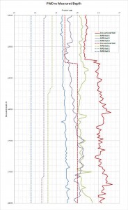
Figure 10 shows the mud weight in and PWD data versus measured depth for the conventional well and the three MPD wells. The graph illustrates the mud weight strategy described previously. The mud weight was decreased progressively from Well 1 to Well 3 while the wells were drilled, and the automated MPD system proved an effective and safe tool to drill the curve and the lateral sections.
The PWD data is also shown for the four wells, and it can be observed that the equivalent BHP was decreased from 15.4 to 14.2 ppg in the curve and from 16.0 to 16.4 ppg to 14.3 ppg in the lateral section. The PWD data has more variations for the first two MPD wells because no SBP was required to maintain the target BHP while drilling. For the third well, these pressure fluctuations are minimized because a lower mud weight was used and surface backpressure was required during drilling and connections.
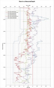
Figure 11 shows the mud weight in and pump rate (gpm) data versus MD for the conventional well and the three MPD wells. There is a correlation between lower mud weights and higher pump rates. With lower mud weights, the stand pipe pressure is also lower because the pump is lifting a lighter mud column. This lower standpipe pressure provides room to increase the flow rate.
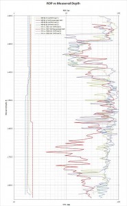
Figure 12 shows the average ROP versus MD for the four wells. The combination of lower mud weight (less solids in the mud) and higher pump rates (better hydraulics) generates higher ROP. The ROP increased mainly while drilling the lateral, but this still resulted in a reduction of drilling days.
Two key factors contributed to this: Different mud weights were used for the various wells at different depths, and significant directional work was required (sliding) while drilling the curves of the MPD wells.
After 16,000-ft MD, the average ROP for the conventional well was about 10 to 20 ft/hr. This average ROP increases up to 50 to 80 ft/hr when looking at the three MPD wells. Higher pump rates also provide the benefit of better hole-cleaning that allows less solids to be kept in the hole that could help to generate less torque and drag and better transmission of weight to the bit.
Figure 13 shows the bottomhole temperature versus MD for the four wells. The combination of lower mud weights (lower friction) and higher pump rates (cooling effect) generates lower bottomhole temperatures. When drilling in high-temperature environments, such as the Haynesville shale, lower bottomhole temperatures could help to mitigate the risk of downhole tools failure, so it could potentially avoid tripping to replace damaged tools.
At 16,626 ft, there was a decrease in the bottomhole temperature of the well 17-2H (solid red line). The reason was that the hole was circulated for a period of 9.5 hrs. After the circulation period, the bottomhole temperature of the well started increasing consistently. There was a MWD failure in the conventional well at 15,764 ft. It correlates with a high temperature spike of 331°F. It is the most probable root cause of the MWD failure. It took 63.5 hrs to get back to drilling.
The curve was drilled faster in the conventional well compared with the other three wells. This is due to additional directional work required (more sliding) to drill these curves, which is mainly influenced by geology. The lateral section was drilled in about 12.2 days in the conventional well. The three lateral sections of the MPD wells were drilled in 4.7, 5.7 and 6.3 days, respectively. This results in a reduction of 62%, 53% and 48% for each well, having an average reduction of 54% for the drilling days.
Conclusion
Shell used different technologies onshore South Texas and North Louisiana Haynesville to optimize operations where conventional drilling would be too expensive and unsafe. A fully automated MPD system allowed a smooth transition from circulating to non-circulating downhole during connection while maintaining continuous rig pump circulation.
This article is based on IADC/SPE 156909, “Onshore US MPD Use by an Operator,” presented at the 2012 SPE/IADC Managed Pressure Drilling and Underbalanced Operations Conference and Exhibition in Milan, Italy, 20–21 March 2012.
Acknowledgements
The authors would like to thank Shell Exploration & Production Company for its support and for allowing the publication of this paper
References
Billa, R., Mota, J., Schneider, B., and Weissman, M. 2011. Drilling Performance Improvement in the Haynesville Shale. Paper SPE/IADC 139842-MS presented at the SPE/IADC Drilling Conference and Exhibition, Amsterdam, The Netherlands, 1-3 March.
Fredericks, P., Sehsah, O., Montilva, J., and Vogelsberg, P. 2010. Experience and Results with a New Automated MPD System while Drilling and Cementing Liner in an Onshore Depleted Gas Field. Paper SPE/IADC 30319-MS presented at the SPE/IADC Managed Pressure Drilling and Underbalanced Operations Conference and Exhibition, Kuala Lumpur, Malaysia, 24-25 February.
Johnson, R., Montilva, J., Sati, M., Grable, J., Saeed, S., Billa, R., and Derise, W. 2011. Field Demonstration of a New Method for Making Drill-Pipe Connections during Managed-Pressure Drilling Operations. Paper 147278-MS presented at the SPE Annual Technical Conference and Exhibition, Denver, Colorado, USA, 30 October-2 November.
Montilva, J., Fredericks, P., and Sehsah, O. 2010. New Scaled-Down Automated Control System Manages Pressure and Return Flow While Drilling and Cementing Production Tubing in Depleted Onshore Field. Paper IADC/SPE 128923-MS presented at the IADC/SPE Drilling Conference and Exhibition, New Orleans, Louisiana, USA, 2-4 February.
Gordon, D., Billa, R., and Weissman, M. 2003. Underbalanced Drilling with Casing Evolution in the South Texas Vicksburg. Paper SPE 84173 presented at the SPE Annual Technical Conference and Exhibition held in Denver, Colorado, U.S.A., 5 – 8 October 2003. Drilling.
Montilva, J., Mota, J., Poletzky, I., Sati, M., Lovorn, R., and Grable, J. 2012. Next-Generation Managed Pressure Drilling System Enables HP/HT Horizontal Wells in the Haynesville Shale. Paper IADC/SPE 151168 presented at the IADC/SPE Drilling Conference and Exhibition held in San Diego, California, USA, 6–8 March 2012.


I leave a response each time I appreciate a post on a website or I have something to valuable to contribute to
the discussion. It is a result of the fire communicated in the post
I browsed. And on this article Onshore MPD system enables lower mud weights for challenging
wells | Drilling Contractor. I was actually moved enough to
post a thought 😛 I actually do have some questions for you if it’s
okay. Is it only me or do a few of the comments appear like written by brain dead people?
😛 And, if you are writing at additional online sites, I would
like to keep up with you. Could you make a list all of all your community pages like your linkedin profile, Facebook
page or twitter feed?
My blog post: Order Testoril
Thank you, you can find us on Facebook, Twitter and LinkedIn by searching Drilling Contractor Magazine.