Risk assessment targets well control functions of MPD operations
Safety barrier analysis of MPD compares primary well control functions with conventional drilling
By Arne Handal, Sondre Øie, Mary Ann Lundteigen, Det Norske Veritas AS
Managed pressure drilling (MPD) is increasingly used in regions where the formation’s operational pressure window is restricted. Det Norske Veritas has seen a considerable demand for third-party evaluation of recently introduced MPD systems. Although they can offer clear advantages compared with conventional drilling, MPD also introduces new and more complex technologies that may influence well barriers.
In this article, the risks associated with the use of such systems is discussed and compared with conventional drilling. This includes a breakdown of a generic MPD system and analyses of equipment that may be used to manage and control flow and pressures in the well. There is currently no method to define well barriers for a generic MPD system. This article suggests a systematic risk assessment approach for determining the role of MPD systems in primary well control. A revised definition of the primary well barrier for MPD is proposed, which will need further discussion in the industry before it can be fully accepted.
Well barriers and risk management
In drilling operations, the main events of concern are related to well kicks and blowouts. A common way to express such risk is by combining the probability of an event with its consequences. Barriers are introduced as a means of risk management, by reducing the probability or severity of the events of concern. They can be defined as measures designed/implemented to reduce the probability of triggering a pre-defined hazard and/or to reduce the consequence of a pre-defined hazardous event.
Frequency-reducing or preventive barriers prevent the hazardous event from occurring, and consequence-reducing or mitigating barriers mitigate the consequences of hazardous events. For a well kick, the primary well barrier is the preventive barrier while the secondary well barrier is the mitigating barrier.
Individual well barrier elements may perform different functions to support the main purpose. A well barrier element can only be considered a well barrier if it can be documented that the element will solely prevent a well incident within both expected and verified operational limits. Otherwise, a combination of several well barrier elements is required.
Because barriers cannot be “designed” fault free, they need to be managed in a way that ensures they perform as intended at all times.
Several models have been proposed to enlighten the relationship between possible deficiencies in barrier performance and the risk of having major accidents. Among these, the “Swiss Cheese Model” is perhaps the most recognized. For drilling operations, the primary and secondary well barrier would make two separate slices in the model.
Barrier deficiencies may be classified as either active failures, caused by humans or technology that has a direct influence on the accident causation, or latent conditions, which are defects or flaws in the system that indirectly allow accident scenarios to develop. Throughout drilling, holes in the Swiss Cheese Model are expected to constantly move and change sizes. For a major accident to happen, holes need to align, allowing for an “accident trajectory.”
Primary well control for MPD
Primary well control with MPD systems may be achieved through active control of BHP. In addition to the mud column, active control of BHP requires an MPD pressure control system. Several concepts exist to adapt the BHP during MPD operations: by adjusting backpressure or manipulating the hydrostatic pressure of the annular mud column.
The MPD pressure control system may be split into four main subsystems:

• An MPD controller unit, located on the rig. It may be used to control the annular hydraulic pressure profile within exposed formation pressure limits through control of dynamic MPD pressure control equipment. For instance, during mud circulation using a closed-loop MPD system, the mud is returned to surface via an MPD choke manifold.
• Monitoring system, with sensors in the well system.
• Dynamic MPD pressure control equipment may be located topside, subsea or downhole. This includes, for example, a valve to continuously adjust the backpressure in the well.
• Static MPD pressure control equipment, used to isolate pressure, may be located topside, subsea or downhole. A rotating control device (RCD) used to contain fluid in the well is considered a static MPD pressure control equipment.
A narrow mud window may require that the MPD controller unit precisely control the open/closed position of dynamic valves, etc, for downhole pressure control. It is therefore important to ensure that the MPD pressure control system is sufficiently reliable. Dependency among the subsystems of MPD pressure control system becomes very important in this context.
With MPD, although the overall purpose of the primary well barrier is to prevent a kick, it is also forcing the industry to rethink the concept of the primary well barrier and how the barrier may involve different equipment without compromising safety.
Conventional drilling operations call for three criteria in the well barrier strategy:
1. Two tested and independent well barriers are required.
2. The primary well barrier is the mud column. The mud weight is designed to hydrostatically overbalance exposed formation pressures. The ECD should not exceed the exposed formation fracture gradient.
3. The secondary well barrier consists of an envelope of several dependent well barrier elements, such as casing and BOP.
With MPD, the first criterion is maintained, but a modification of the second criterion is needed: The primary well barrier is the same as for  conventional drilling if the mud is designed to solely prevent a well incident within both expected and verified formation pressure limits. If not, the primary well barrier is ensured by the mud in the well in addition to dedicated equipment of the MPD pressure control system. This means that new technology introduced with the primary barrier needs to be qualified for its intended use.
The third criterion is maintained as long as the well is brought to conventional mode if the primary well barrier fails.
Introducing new barrier elements into the primary well barrier must be performed without introducing new vulnerabilities. Therefore, it is proposed to add a fourth criterion to the MPD well barrier strategy: Equipment of the MPD pressure control system shall be considered an adequate primary well barrier element only if it is independent of the secondary well barrier. Otherwise, a suitable-for-purpose risk assessment shall be performed to document that a sufficient level of independence between the two well barriers is still ensured.
This means, for example, that the MPD controller unit should be independent of the BOP control system.
Current drilling-related standards provide little guidance or specific requirements about the reliability performance of the primary and secondary well barrier. One exception is Norway’s OLF 070 (2004) guideline, which applies for safety instrumented systems. It describes a minimum level of performance for commonly used offshore safety functions and is expressed in safety integrity level (SIL). SIL is the preferred measure of reliability in international standards for safety instrumented systems, such as IEC 61508 (2010) and IEC 61511 (2003). The standards
distinguish among four levels – SIL 1 to SIL 4.
OLF 070 does not suggest a minimum SIL requirement for mud circulation, while an SIL 2 requirement is specified for BOP functions.
With no minimum reliability performance specified for the primary well barrier in the industry, it is therefore suggested to compare the reliability of MPD with the reliability that may be assumed with hydrostatic overbalance in the mud column.
Ideally, the comparison should be quantitative and qualitative. However, in this article the analysis is limited to a qualitative assessment due to the lack of data to support the quantitative analysis. If data is available, the approach may be easily extended to a quantitative analysis.
Risk assessment of MPD for primary well control
A risk assessment, with focus on the reliability properties of the new primary well barrier concept with MPD, has been performed by three main steps:
1. Physical breakdown of the system, to identify all components that may be part of the new primary well barrier concept.
2. Function definition and functional analysis, to create a structured breakdown of the overall function of primary well control for MPD. The analysis defines each function that would be performed by MPD equipment.
3. Fault tree analysis, to relate the loss of primary well control to underlying causes and events. The fault tree contains both the conventional and MPD barrier elements, but a comparison is made of the effectiveness of the two approaches given a narrow mud window formation.
Physical breakdown
of system
A generic description was made of the four subsystems in the MPD pressure control system. This will allow for a systematic description of all relevant equipment used to execute MPD operations. One technical improvement, currently not adopted by the industry, is to separate the safety and non-safety functions into different physical units.
1. MPD controller unit:
This is the control logic unit used to perform arithmetic and logical operations, including:
• Interface to dynamic and static MPD pressure control equipment;
• Interface to hydraulics and mechanistic models;
• Connection to internal well monitor system (e.g., system-specific pressure transmitter, flow meter, etc);
• Connection to external well monitoring systems (e.g., mud volume control);
• Connection to drilling control system;
• Interface/connection to other relevant systems;
• Hydraulics models used to simulate physical parameters of fluid in well in addition to flow, pressures and temperatures;
• Mechanistic models used to simulate other relevant operational parameters (e.g., torque and drag, ROP, formation conditions, etc); and
• Safety logic unit used to perform dedicated safety functions.
When the MPD pressure control system is used for primary well control, it is important to recognize that some of the system functions will be defined as safety-critical. Since MPD pressure control systems fall into the definition of safety instrumented systems, it is necessary to adhere to standards, such as IEC 61508 and IEC 61511, for these functions. An important principle advocated in the IEC standards is placing safety and non-safety functions in different and independent systems, or otherwise build the system as if all functions were safety-critical. It is
therefore suggested that safety functions are placed in a new logic unit dedicated to safety and that this logic unit is designed according to the mentioned standards.
2. Well monitoring system
This is used to monitor operational parameters and to give input to the MPD control system. It includes internal and external monitoring systems. While internal monitoring systems are part of the MPD system, external monitoring systems are typically provided by service companies.
Measuring devices (or sensors) to monitor well and dynamic and static MPD pressure control equipment include:
• Pressure transmitters located close to dynamic or passive MPD pressure control equipment;
• Flow meters measuring mud return flow through mud return lines, MPD choke manifolds, etc; and
• Other relevant measurements, such as level and temperature transmitters.
All measuring devices are read by the control logic unit. Signals from measuring devices that are needed for the primary well barrier, i.e., the well barrier elements, must be replicated for the purpose of being read by the safety logic unit, using dedicated cables/signal transfer as close as possible to the measuring device. Using the control logic unit to replicate this information is not allowed, as this would make the safety system dependent on a non-safety system.
3. Dynamic MPD pressure control equipment
This is used to dynamically adapt the annular hydraulic pressure profile and includes:
• (Automated) MPD choke manifold to regulate annular hydraulic backpressure and mud return flow:
– Adjustable chokes to regulate mud return flow.
• Conventional pumps to circulate or pump fluid or cement:
– Rig pumps to circulate fluid into well;
– Booster pump to pump fluid into marine riser; and
– Cementing unit to pump cement or mud into well.
• Additional circulating systems connected to the well, used to manipulate mud flow, includes:
– Backpressure pump to maintain flow through (automated) MPD choke manifold;
– Separate injection line to mix gas or fluid with the drilling fluid in the well;
– Subsea pump to adjust mud return flow;
– Separate mud return line to conduct mud return flow back to surface; and
– Bypass line to conduct and regulate mud return flow.
• Dedicated tools used to restrict flow in drill string or in well include:
– Inside drill string valve to prevent U-tubing between drill string and wellbore;
– Valve to prevent U-tubing between mud return line and well;
– ECD reduction tool to reduce the impact of (annular) friction loss on the BHP; and
– Additional annular preventers that are not part of the BOP stack to seal the well and maintain backpressure.
The control logic unit will interface dynamic MPD pressure control equipment. For equipment that also acts as a primary well barrier element, an independent means of activation from the
safety logic unit is needed. Commands from the safety logic unit should overrule any command from the control logic unit.
4. Static MPD pressure control equipment
This is used to isolate backpressure and includes:
• Rotating BOP or rotating control device (RCD) to close the well system and maintain backpressure;
• Non-rotating control device (NRCD) to close the well system and maintain backpressure; and
• Tubing to isolate pressure.
– Drill string to prevent unintentional flow between drill string and well.
Note that not all devices within the MPD pressure control system are well barrier elements. Only the components whose failure may result in the failure of the primary well barrier are defined as well barrier elements.
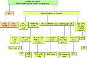
With basis in these descriptions, the physical breakdown of the system used for primary well control may be illustrated by the technical hierarchy shown in Figure 1 for a closed MPD well system using backpressure to adjust BHP.
Description of a simplified MPD system
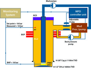
A case study involving a simplified closed MPD well system (Figure 2) will be used to illustrate the relationship between the MPD pressure control system and the primary well barrier.
Under steady-state conditions, the pressure seen at the bottom of the well is the sum of the hydrostatic pressure of the mud column, plus the hydraulic friction loss in the annulus and the backpressure below the RCD. To adjust the pressure profile throughout the wellbore, the drilling fluid is returned to surface via an MPD choke manifold. The manifold is simplified to one adjustable choke that is used to regulate the return flow and thus the backpressure.
An MPD controller unit is connected to the respective choke. For precise control, the MPD control system is connected to a well monitoring system that receives information from different measuring devices in the well. The monitoring system may involve internal and external monitoring systems. Important feedback from the well system is given by the pressure transmitter and the PWD data, in addition to other measuring devices like flow meter and standpipe pressure.
Data is continuously sent to the MPD controller unit from the monitoring systems. The MPD controller unit controls the annular pressure in the well by ensuring that the measured pressure below the RCD is the same as the predetermined set point within a certain margin. When measured pressure is higher than set point, the choke will be opened while the opposite will result in choking. Change in the mud pump rate will involve subsequent control of choke position as long as the pressure set point is the same.
A backpressure pump is normally used to ensure sufficient flow through the adjustable choke such that the BHP is maintained. The static pressure in the annulus is larger than the static pressure in the drill string during drill pipe connection. A drill string non-return valve is therefore placed above the bit to prevent back flow.
In light of the generic description of MPD subsystems, the control and safety functions may be implemented as shown in Figure 3. The reliability of the MPD controller unit must be high enough to maintain the BHP within the narrow drilling window. If the logic unit fails to control the BHP, the safety logic unit will take over and effectively bring the well into a safer mode. It is recommended that a minimum of functions are implemented in the safety logic unit; only those required to bring the well into a safer mode. A safer mode shall prevent a further loss of control and will depend on the well, the drilling system and its design, and operational limitations.
Case study
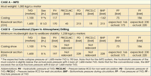
A case study has been constructed with basis in the well data summarized in Table 1 and the closed MPD system introduced in Figure 2. As can be seen from Table 1, the well cannot be drilled conventionally without fracturing the formation; therefore, the closed MPD system is more suitable for drilling of the 8 ½-in. hole section.
With MPD, the mud weight is slightly underbalanced compared with the actual pore pressure. A certain backpressure is needed to drill the well overbalanced. Loss of backpressure will cause degraded primary well control. The control of backpressure is therefore essential and will depend on components such as the RCD, the adjustable choke, the backpressure pump, the mud pumps, the drill string non-return valve, the drill string, the monitoring system and the MPD controller unit. Respective components are part of the MPD pressure control system, but further evaluations are required to decide which equipment are well barrier elements.
Functional analysis
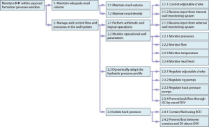
The functions of the different components have been mapped into a function tree (Figure 4). The identification of all functions starts with a high-level description of the purpose of the primary well barrier and continues with the definition of sub-functions according to the physical breakdown of the system.
As can be seen from Figure 4, the main function is to keep the BHP within the drilling window. The functional breakdown may be conducted by iteratively asking how an established function is achieved, and the results may be presented in a function tree.
Based on the insight gained from the function tree, a fault tree may be constructed to illustrate the combinations of failures that may lead to a loss of primary well control.
Fault tree analysis
A fault tree is used to illustrate how various types of events contribute to loss of primary well control. The main elements of a fault tree are the “top” event, “and” gates, “or” gates and basic events. The “top” event is overall system failure, which in our case is the non-fulfillment of primary well control. Both “and” as well as “or” gates are logic gates that relate an output event description to a set of input events. A basic event represents the lowest level of input events, and a transfer gate is a link to a separate sheet for further development of the fault tree.
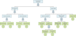
The fault tree developed for complete loss of well control is shown in Figure 5. As illustrated, this “top” event will occur if “loss of primary well control” and “loss of secondary well control” are present at the same time. It is assumed that secondary well control for MPD is the same as for conventional drilling.
A more detailed fault tree was developed for loss of primary well control (Figure 6). The fault tree has been divided into two main parts: The conditions underlying the failure of mud provision (left) and the conditions underlying the failure of the MPD system (right).
At first glance, the left side seems to be identical to the events and conditions leading to loss of conventional primary well control. Without further considerations, it would seem pointless to introduce MPD for primary well control, as the right side of the fault tree just adds more ways for loss of primary well control. It is, however, necessary with a more thorough analysis of the underlying premises. The probabilities or frequencies of events leading to primary well control failure for conventional drilling and for MPD will be quite different due to the different systems and drilling conditions.
A well can be impractical to drill conventionally based on data in Table 1. For the case study, it is given that the closed MPD system is more suitable.
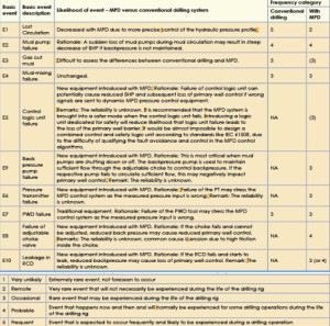
In this article, the assessment is made qualitatively and the results summarized in Table 2. A set of frequency categories indicates the rate of occurrence of events for conventional drilling and drilling with MPD, and bear in mind that the selection of categories has been based on the authors’ best knowledge. The results can later be supported by a quantitative analysis if relevant data is available.
As seen from Table 2, the loss of primary well control will occur frequently (5) if conventional drilling is chosen, while this situation is reduced to occasional (3) with MPD. This latter argument is deduced by a brief assessment of the events leading to failure loss of mud control:
Failure to provide mud (with conventional drilling): This failure frequency is summed up by the frequencies of all underlying basic events. In total, we may expect that the failure to provide mud falls into the “frequent” category, as the loss of circulation is assumed to fall into this category.
Failure to provide mud (with MPD): This failure frequency is summed up by the frequencies of all underlying basic events. In total, we may expect that the failure to provide mud falls into the “occasional” to “probable” category. In this case, it is failure of mud pumps and mud mixing that contributes the most to failure of mud provision.
Failure of MPD: This occurs if failure of control with BHP or failure to control backpressure and leakage through RCD. The sum of the frequencies of these failures is, therefore, an indication of how often an MPD failure is experienced.
• The failure of BHP control is most likely dominated by the failure rate of the logic controller, as the simultaneous failure of PWD and pressure transmitter is less likely. Assuming that a safety logic unit is introduced, it may be expected that this rate is low and in the “occasional” to “remote” category.
• Failure to control backpressure may be assumed to fall into the “occasional” category as this failure occurs only if the backpressure pump and choke valve fail in the same time period.
• Failure in RCD has been assumed to fall into the “occasional” or “probable” category.
Summed up, the frequency of MPD failure may be in the “occasional” to “probable” category. Overall, it may be expected that, in this scenario, drilling with MPD will experience occasional to probable loss of primary well control, whereas a loss of primary well control may occur frequently with conventional drilling.
Discussion and conclusions
MPD used for primary well control involves new equipment, new methods and new ways of using existing technology. Frameworks on the qualification of new technology, such as DNV-RP-A203 (2012), may be useful to ensure that the risks associated with “the new” are identified and sufficiently treated.
This article may be seen as a first attempt to help the industry better understand how the overall drilling risk may change with MPD systems. It is pointed out that the approach should be considered as a first step, and further research and industrial competence should be joined to improve risk management with MPD.
The risk analysis made in this article has been qualitative and based on a simple generic MPD system. It would be of interest to analyze a real MPD system in a similar way.
Improving well control reliability by adding redundancy to the MPD system should also be investigated. Redundancy as such has not been studied in this work. To enhance the confidence of future analyses, it is necessary to collect data on the performance of MPD equipment.
Click here to register for access to an online MPD screening tool developed by the IADC UBO & MPD Committee. The tool helps the industry to determine when and how to deploy the appropriate MPD technologies.
This article is based on a presentation at the 2013 IADC/SPE MPD & UBO Conference & Exhibition, 17-18 April in San Antonio, Texas.
References
API/IADC (2012). Recommended Practices Managed Pressure Drilling (MPD) Operations.
BP (2010). Deepwater Horizon Accident Investigation Report. www.bp.com
DNV-RP-A203 (2012). Qualification of New Technology. Høvik: Det Norske Veritas (DNV)
Falk, K., Fossli, B., Lagerberg, C., Handal, A., and Sangesland, S.: ”Well Control When Drilling With a Partly-Evacuated Marine Drilling Riser,” Paper No. 143095, presented at the IADC/SPE Managed Pressure Drilling and Underbalanced Operations, 5-6 April 2011, Denver, Colorado, USA
Handal, A.: “Gas Influx Handling for Dual Gradient Drilling,” Doctoral Theses at Norwegian University of Science and Technology in 2011
Hollnagel, E. (2008). Risk + barriers = safety? Safety Science, 46, 221-229.
Hopkins, A. (2011). The Disastrous Decisions: The Human and Organisational Causes of the Gulf of Mexico Blowout. Sydney: CCH Australia Limited.
IADC, Underbalanced and Managed Pressure Drilling operations (2012). HSE Planning Guidelines . 9th rev.
IEC 61508 (2010). Functional safety of electrical/electronic/programmable electronic safety-related systems. Geneva: International Electrotechnical Commission.
IEC 61511 (2003). Functional safety – Safety instrumented systems for the process industry sector. Geneva: International Electrotechnical Commission.
ISO 13702 (1999). Petrolem and natural gas industries – Control and mitigation of fires and explosions on offshore production plattforms – Requirements and guidelines. Geneva: International Organization for Standardization.
ISO GUIDE 73 (2009). Risk management – Vocabulary. Switzerland: International Organization for Standardization.
NORSOK D-010 (2004). Well integrity in drilling and well operations. 3rd rev. Lysaker: Standards Norway.
NORSOK Z-013 (2010). Risk and emergency preparedness assessment. 3rd ed. Lysaker: Standards Norway.
OGP (2012). Recommendations for enhancements to well control training, examination and certification. Report No. 476.
OLF 070 (2004). 070 Guidelines for the Application of IEC 61508 and IEC 61511 in the petroleum activities on the continental shelf. Stavanger: Norsk Olje og Gass.
PSA (2012). Prinsipper for barrierestyring i petroleumsvirksomheten. Høringsutkast, www.ptil.no
Rausand, M. & Høyland, A. (2004). System Reliability Theory: Models, Statistical Methods, and Applications. 2nd. ed. Hoboken NJ: John Wiley & Sons.
Rausand, M (2011). Risk Assessment: Theory Methods, and Applications. 1st ed. Hoboken NJ: John Wiley & Sons.
Reason, J. (1997). Managing the Risks of Organizational Accidents. Burlington: Ashgate Publishing Compay.
Saad, S., Lovorn, R., and Knudsen, K. A.: ”Automated Drilling Systems for MPD-The Reality,” Paper No. 151416 presented at the 2012 IADC/SPE Drilling Conference and Exhibition, 6-8 March, 2012, San Diego, California
Skjerve, A.B.M, Rosness, R. Aase, K., & Bye, A. (2002). Mennesket som sikkerhetsbarriere i en organisatorisk kontekst. IFE/HR/E-2003/023. IFE.
Sklet, S. (2006). Safety barriers: Definition, classification, and performance. Journal of Loss Prevention in the Process Industries, 19, 494–506.
Statoil (2010). Granskningsrapport COA INV Intern ulykkesgranskning: Brønnhendelse på Gullfaks C.




After working with Weatherford MPD in Brasil for two years, I think real highly and I am confident of the system and the way it works. I was amazed of the results we had. The system was primarily used to drill through a tight tolerance zone for Petrobras and ended up being used for kick detection afterwards.
The time added on to drilling the well nearly doubled. The BOP testing was extended with additional well bore valves and riser to be tested. Installing and removing BART, bearring assembly, into the RCD was very time consuming. Many times during drilling, the need to pick up off bottom and perform a dynamic flow check was necessary dure to inaccurate mechanical flow meter in would malfunction and show the MPD system either a increase or decrease in flow.
A very expensive and hard to get mud was used to achieved accurate flow in / flow out readings with MPD due to compressablility of conventional drilling mud. The mud, called WARP mud, had barite molicules smaller than blood cells, making the compression factor much lower and alowing barite to remain suspended even when static. This was the only time saving advantage of using MPD, which allowed driller to extend choke and kill line flushing time to up to a week each time.
With this being said i have a difficult time believing that MPD operation will be the route that contactors choose to ensure a safe means of well control. Like I said before i enjoyed the experience of using the MPD system and hope to have the opportunity to work with it again, but I doubt the very expensive and time compuming piping additions will be added to drilling rigs primarily for kick detection and means of well control.
Quentin Guidry
Diamond Offshore Driller
Fantastic analysis ! I loved the information ! Does anyone know where my company can get access to a sample a form version to fill out ?