Upgrades extend drilling capabilities of Beryl platform rigs
Enhancements of ERD capacity, well control system enable near-field development wells
By Miguel O. Mota, Gregory W. King, ExxonMobil Development Company; William D. O’Donnell, ExxonMobil Production Company; Kerr Hewit, KCA DEUTAG – RDS; Paul A. Dumont, Shell Exploration & Production
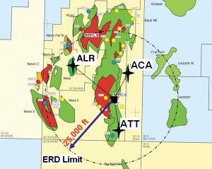
accumulations that had not been developed, an ERD upgrade for the drilling rigs on the Beryl Alpha platform was conducted over two stages to extend the drilling radius from 15,000 ft to 25,000 ft.
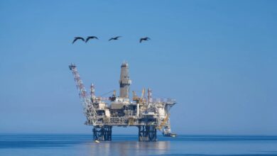
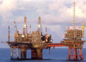
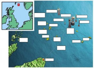
The Beryl field, located about 200 miles northeast of Aberdeen, is located in a water depth of 390 ft. Its discovery in 1972 led to the installation of the Beryl Alpha platform in 1976 and the Beryl Bravo platform in 1984. The Beryl Alpha platform is a 40-slot twin drilling rig, three-leg concrete structure with storage capacity in its base for more than 1 million bbl of oil. The Beryl Bravo platform is a 21-slot single drilling rig steel-jacket structure with an oil export line to the Beryl Alpha platform. Oil export from the field is by tanker loading from a single point mooring. Gas export from the field is via the SAGE pipeline.
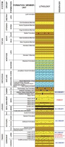
The field is made up of heavily faulted and stratigraphically complex Jurassic and Triassic sandstone reservoir intervals. It consists of one primary reservoir, Beryl, and five secondary reservoirs – Katrine/Nevis, Linnhe, Nansen/Eiriksson, Lewis, and Cormorant (Figure 2). The challenge of developing this asset has been achieved by identifying and implementing new practices and technologies throughout its life, allowing the production of over 1 billion bbl of oil and over 3 trillion cu ft of gas.
When the extended-reach drilling (ERD) upgrade was conceived at the end of 2006, a total of 223 wells had been drilled to develop the Beryl field and its satellites (81 from the Beryl Alpha platform, 70 from the Beryl Bravo platform and 72 subsea wells). To enable drilling the next generation of platform wells, the drilling radius and maximum working pressure (MWP) capabilities of the Beryl Alpha platform (Figure 3) had to be extended.
ERD upgrade
Nevis, Ness, Buckland and Skene are subsea satellite fields supported by the Beryl Alpha platform. Several other accumulations exist that have not been developed but were considered potential future subsea satellite development opportunities (Figure 1). Driven by the sharp cost increase in subsea satellite developments in early 2000, development of these wells was not seen as a viable option. It was decided to evaluate the potential to develop these accumulations with ERD wells.
In 2006, a multifunctional team analysis indicated that a drilling radius of 30,000 ft was required to reach all of these with ERD wells.
A preliminary assessment showed that complete replacement of the drilling rig equipment, including both derrick structures, was required to reach all available opportunities. The project was deemed too expensive, and it would have taken more than two years of planning and construction time; therefore, this option was ruled out.
The next iteration focused on enhancing the capabilities of the existing drilling rig equipment. The subsequent evaluation assessed it was possible to extend the drilling radius from 15,000 ft to 25,000 ft within the constraint of using the existing drilling rig equipment. This ERD upgrade would allow reaching some of the potential targets with ERD wells.
To define the scope of the ERD upgrade, preliminary well designs were developed. Drilling engineering analysis on those upgrades was required to enhance rig torque capabilities, pump hydraulics capabilities, and pipe-handling and storage capabilities.
Rig Torque Capabilities
The original kelly-oriented derricks could not support a conventional dolly-mounted top drive. In 1995, these were retrofitted with a DC top drive 34,000 ft-lbs hanging torque-tube device. The planned ERD wells required a higher torque capability. In 2006, there were only two top drive systems with a similar torque-tube device and the required higher torque capability, and only one could be delivered to meet the project schedule. This was an AC top drive 43,000 ft-lbs hanging torque-tube device. The plan was to refurbish and reuse the existing torque-tube, intermediate tiebacks, travelling blocks and becket.
Pump Hydraulics Capability
The legacy of having two rigs with two pumps each greatly benefitted the ERD upgrade as it allowed the use of four pumps on one rig. The intention for future drilling programs from the Beryl Alpha platform is to operate one rig at a time. Sufficient horsepower was available, but the pressure rating of the pumps had to be increased. Analysis indicated it would be possible to increase the circulating system pressure rating from 5,000 psi to 7,500 psi. This required upgrading the fluid end modules, pulsation dampeners, pressure indicators and transmitters, pressure gauges, mud pump pressure relief valves, and mud system pipe work.
Pipe Handling & Storage
The racking capacity of both Beryl Alpha platform derricks is 19,000 ft of 5-in. drill pipe. Due to the design of the derrick structures, racking capacity could not be increased. ERD wells with a drilling radius of 25,000 ft were expected to have a total measured depth of 30,000 ft. Hence, racking capacity constraints impose picking up and laying down up to 11,000 ft (350 singles) during tripping operations.
This meant dependence on weather-sensitive platform crane operations, especially during winter operations, as platform cranes cannot operate above 40-knot winds. This translates into additional risk exposure. Due to the scale of manual work required when picking up and laying down, safety considerations were also of significant importance. To mitigate these risks, analysis indicated that mechanization of the tripping process was preferred over automation. The proposed solution integrated the following components: pipe deck machine, pipe transferring conveyor with pipe tailer, and power elevators on tiltable links from the top drive.
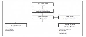
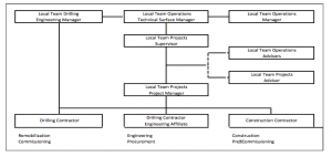
The organizational setup used to execute the ERD upgrade consisted of a drilling projects adviser as the focal point for the contractors, managing the upgrade project and the platform maintenance.
The engineering affiliate of the drilling contractor managed the project through all phases, from engineering to construction. This leveraged the drilling contractor’s familiarity with Beryl Alpha platform, assisting the simultaneous execution of the ERD upgrade with required platform maintenance. It was believed the use of an external construction organization unfamiliar with drilling operations would not be as efficient.
The mechanical completion date for the ERD upgrade was projected to take six months. The actual mechanical completion date was two months behind the original date. The original date was not attained due to equipment delivery issues and the inability to realize the expected synergies from the employed organizational setup strategy. The final cost of the ERD upgrade was about 20% above the original approved budget.
After finishing the ERD upgrade in early 2007, ALO (A82x, A82w) well drilling operations started; however, the well was later temporarily plugged and abandoned at the 9 5/8-in. casing shoe. A combination of factors, including complex geology and wellbore instability, was attributed to the unsuccessful attempt to drill the ALO (A82x, A82w) 8 ½-in. hole section.
The rig was cold-stacked while multifunctional teams conducted extensive analysis to understand the challenges and mature other opportunities for the next drilling program.
Well control system
Potential development opportunities for the next drilling program required extending the MWP from 5,000 psi to 10,000 psi. The well control system upgrades involved the renovation of the blowout preventer (BOP) and control panels, choke and kill system, and high-pressure mud manifold. Certain modifications also had to be made to meet current regulations and recommended practices involving BOP-handling equipment, drip pan/bell nipple seal housing, mud gas separator system, access walkways, emergency escape and trip tank system.
Lessons learned from the ERD upgrade showed that a new execution approach was required for the well control system upgrade. Hence, at the early stages of front end engineering design (FEED), the drill team influenced the projects team to assume a leading role in the well control system upgrade.
An organizational setup strategy was co-developed by the drilling and projects teams that leverage the strengths of all parties involved. The engineering affiliate of the drilling contractor was retained to execute the engineering and procurement. Offshore implementation duty was assigned to the projects team’s primary contractor. The contractor had the Beryl platforms construction expertise to ensure offshore alignment and optimize costs and schedule.
Project management responsibilities were transferred from the drilling team to the projects team, allowing for company project management processes and best practices to be leveraged in the planning and execution of the well control system upgrade.
The team pursued accelerating the upgrade project schedule to meet full funding basis through a combination of project scope reduction and construction optimization. The project scope reduction was achieved by challenging the justification of each component in the project scope and testing and justifying deviations to use existing equipment that did not comply with the recommended practice.
Even though FEED was complete, this approach led to the elimination of some items (i.e., instrumentation upgrade), deferred delivery and installation of others (i.e., glycol dehydration skid) and justification to use existing equipment that did not comply with recommended practice (i.e., trip tank system). The construction optimization was attained by maximizing onshore fabrication through a modular approach to systems and by guiding engineering and contractors into co-developing a construction driven schedule. The modular fabrication strategy was used on several systems (i.e., choke and kill system skid).
The construction-driven schedule was accomplished by changing the engineering-driven model used by the engineering contractor. The first step was to maximize work fronts vertically by erecting a solid scaffolding mezzanine level called the “dance” floor in the rig substructure, where most of the construction activity was taking place.
Then, the construction contractor developed an optimum construction sequence for each work front and fed that back to the engineering contractor. The engineering contractor divided systems into work front-based subsystems and realigned the engineering effort to produce deliverables required to initiate procurement and work pack development to meet the construction schedule. Finally, a critical path tracking by work front was put in place. This completed the shift from an engineering-driven schedule to a construction-driven schedule.
These efforts were expected to accelerate the forecasted mechanical completion date by three months. The actual mechanical completion date was two months ahead of the original date. The accelerated forecasted mechanical completion date was not achieved due to a combination of delivery and quality procurement issues, as well as construction growth from the original estimate that could not be offset with additional manpower.
The final cost of the well control system upgrade was about 10% below the approved budget.
Well design
Final well design was constrained by available donor wells, target location and the capabilities of available equipment. An additional constraint was the elevated cost and inherent risks of recovering the slot to the 20-in. casing shoe. Thus, the shallowest potential sidetrack started out of the existing 13 3/8-in. casing.
If required, access to the 13 3/8-in. casing string was achieved by cutting and pulling the existing 9 5/8-in. casing, then setting a whipstock inside the 13 3/8-in. casing. After milling a window, the 12 ¼-in. hole is drilled through highly reactive Tertiary shale and/or highly porous and unconsolidated Tertiary sands until reaching section TD to at least the top of the Maureen formation (Figure 2). Inclination through this interval was maintained to about 45°.
The 12 ¼-in. hole section is typically drilled with 9.0 to 9.5 ppg water-based mud to allow drilling all open formations in this interval in one hole section.
The 9 5/8-in. production casing was run and cemented. The well displaced with 12.0 to 12.5 ppg non-aqueous fluid, which is required for wellbore stability. Then, the bulk of the horizontal displacement required for the well is drilled in the 8 ½-in. hole, which was drilled through the Maureen and Jorsalfare formations until reaching section TD at the top of the targeted reservoir. Inclination is built to about 90° before dropping inclination in order to hit the well targets.
The 7-in. intermediate/production liner was run and cemented. This liner is needed for two reasons:
• It protects the long horizontal displacement interval, and
• It allows the mudweight to be reduced before drilling the 6-in. production hole into a potentially depleted reservoir.
Due to the uncertainty of the mudweight required for wellbore stability in the long horizontal displacement interval and extent of reservoir depletion, this strategy mitigated potential wellbore stability issues in the long horizontal displacement interval and fracture-induced losses in the potentially depleted reservoir.
Finally, the 6-in. hole was drilled through the targeted reservoir to section TD defined by geological and production requirements. The 4 ½-in. production liner was then run. Depending on the reservoir characteristics, this liner could be predrilled or cemented and perforated. Unless a cemented and perforated liner proves economically superior, a pre-drilled liner is preferred. The use of a predrilled production liner significantly simplified completion operations. Finally, the well was completed with a 5 ½-in. x 4 ½-in. tubing string.
Three–well ERD program
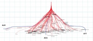
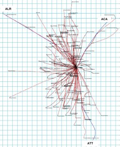
ACA (A83z) was the first well drilled in the program (Figures 1, 4 and 5). Once its donor well was successfully abandoned, the slot was recovered by cutting and pulling the 9 5/8-in. casing and setting a whipstock, then milling a window in the 13 3/8-in. casing at about 7,600-ft MD. The 12 ¼-in. hole was drilled to the top of the Jorsalfare at about 11,900-ft MD. The 9 5/8-in. casing was run and cemented.
The 8 ½-in. hole was drilled to the top of the Cormorant reservoir, followed by drilling the 6-in. hole through the Cormorant reservoir 18,390 ft MD. The 4 ½-in. predrilled liner was run and set.
The 5 ½-in. x 4 ½-in. tubing string was run and set. ACA (A83z) was the first 10,000-psi well drilled from the Beryl Alpha platform.
ALR (A82v) – ALO redrill – was the second well drilled in the program (Figures 1, 4 and 5). The slot was recovered by cleaning out the 9 5/8-in. casing of the original ALO (A82x, A82w). The 8 ½-in. hole was drilled from the 9 5/8-in. casing shoe in the Maureen formation at about 10,900-ft MD to the top of the Katrine/Nevis reservoir at about 23,800-ft MD. The 7-in. liner was run, set and cemented.
The 6-in. hole was drilled through the Katrine/Nevis reservoir to TD of 24,650-ft MD. The 4 ½-in. predrilled liner was run and set.
The 5 ½- x 4 ½-in. tubing string was run and set. ALR (A82v) is the longest well drilled in the Beryl field.
ATT (A84z) was the third well drilled in the program (Figures 1, 4 and 5). After abandoning its donor well, the slot was recovered by setting a whipstock and milling a window in the 9 5/8-in. casing at about 12,700-ft MD. The 8 ½-in. hole was drilled to the top of the Lewis reservoir at about 21,400-ft MD. The 7-in. liner was run, set and cemented.
The 6-in. hole was drilled through the Lewis reservoir to TD of 22,415-ft MD. The 4 ½-in. predrilled liner was run and set. The 5 ½- x 4 ½-in. tubing string was run and set. ATT (A84z) is the second-longest well drilled in the Beryl field.
Learnings from ERD program
Donor Well (Slot) Risk Considerations
All wells drilled in the three-well ERD program were new redrilled wells from previously drilled wells. The new redrilled wells were the third wells to be drilled from their respective platform slot. This presents unique set of challenges not seen in new field developments with world-class ERD wells.
The slots used for ACA (A83z) and ALR (A82v) had shallow, high-dogleg severity intervals, which affect all operations to be executed in which equipment capabilities are being pushed to their limits. This should be taken into consideration when planning and executing a new redrilled well.
The slot used for ATT (A84z) had the 9 5/8-in. production casing string run in its first well 20 years earlier. ATT (A84z) was a whipstock sidetrack out of this 9 5/8-in. production casing. Reuse of production casing and production liner strings may require evaluating casing conditions during slot recovery operations to ensure wellbore integrity of the new redrilled well.
Another risk to consider is the abandonment status of wells abandoned before the donor well to the new redrilled well. After executing abandonment operations on the donor well (A69) to ACA (A83z), increased gas levels were observed during slot recovery operations. Mudweight was significantly increased to reduce gas levels. After investigating the slot history, it is likely the problems were a legacy from the abandonment of the first well drilled from this slot (A63).
Drilling Strategy Through Unstable Shale
Unprecedented wellbore instability caused the failure of the 8 ½-in. hole interval in the original ALO (A82x and A82w) well. The planning of ALR (A82v) began almost immediately and involved the combined efforts of a multifunctional team consisting of the local drill team, local geoscience team, industry experts from the operator and the other Beryl field co-venturers.
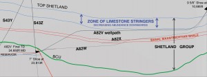
After extensive work by the multifunctional team, the presence of previously unidentified unstable shale throughout the Beryl field was noted. This unstable shale was named the Basal Maastrichtan shale (BMS). It was determined that unsuccessful attempts to drill ALO (A82x, A82w) were the results of a combination of factors. These included well path relative angle to BMS bedding plane, formation lithology, mudweight and open-hole time.
Each factor had been managed on previous Beryl field wells independently. The combination of these factors in the same hole section, however, led to the unsuccessful attempt. In addition to ALO (A82x, A82w), 14 other wells have been drilled through the BMS with a well path inclination above 60°. All wells drilled with mudweight above 10.0 ppg and well path relative angle to BMS bedding plane above 20° did not experience significant wellbore stability problems.
Hence, ALR (A82v) was designed as follows:
• Well path relative angle to BMS bedding plane was increased to 20° (this also decreased measured depth drilled through BMS);
• Mudweight was maximized to prioritize wellbore stability over lost returns; and
• BMS open-hole time was minimized.
ALR (A82v) was successfully drilled using the described strategy through the BMS without signs of wellbore stability problems (Figure 6). ATT (A84z) was successfully drilled using the same strategy through the BMS. Proven successful, the drilling strategy through the BMS has become an integral part of the multifunctional team’s toolkit for the planning and execution of future wells. Upcoming Beryl field wells have been planned to make full use of it.
Intermediate/Production Liner String Risks
After successfully drilling the 8 ½-in. hole interval, the 7-in. intermediate/production liner needed to be run, set and cemented before proceeding to drill the 6-in. production hole. During the planning stage of the three-well ERD program, it was determined that using the following items improved the operational success of getting the 7-in. liner to bottom:
• Aluminum PDC-like carbide-cutting structure eccentric nose reamer shoe;
• Three centralizers per two joints on entire 7-in. liner, and
• Hydraulic-set liner hanger with a hydraulic lock/mechanical release liner hanger running tool.
Based on torque and drag modeling with in-house and third-party software, running the 7-in. liner conventionally (i.e., mud over mud) was expected to get it to bottom without rotation. In addition, the same torque and drag modeling showed that, if required, the 7-in. liner could be rotated within the system limits. At this point, the drilling strategy through the BMS had not been tested. Hence, rotating the 7-in. liner was considered possible. For this reason, the aluminum PDC-like carbide-cutting structure nose eccentric reamer shoe and the hydraulic-set liner hanger with a hydraulics lock/mechanical release liner hanger-running tool were incorporated.
The former provided cutting structure and geometric profile to aid 7-in. liner passage and/or rotation through ledges. The latter provided the ability to rotate the 7-in. liner without the concern of inadvertently releasing the liner hanger from the liner hanger-running tool.
Finally, it was understood that the use of the aforementioned centralization strategy would mitigate expected drag while running the 7-in. liner.
While running the 7-in. liner on ALR (A82v), the following observations were made:
• Drag was much higher than anticipated;
• The 7-in. liner could not be rotated within system limits; and
• The 7-in. liner would not go past 15,117-ft MD, which was about 8,700 ft from bottom.
After pulling out of the hole and laying down the 7-in. liner and analyzing available information, the following changes were made for the second attempt to run the 7-in. liner:
• All centralizers were removed from the 7-in. liner except those on the shoetrack;
• The hydraulic lock/mechanical release liner hanger-running tool was replaced with a hydraulic lock/hydraulic release liner hanger running tool; and
• The 7-in. liner was to be run with partial flotation (i.e., base oil over mud).
The removal of the centralizers reduced the stiffness and potentially the drag of the 7-in. liner. The change of the liner hanger-running tool provided a higher torque rating tool (37,000 ft-lbs versus 25,000 ft-lbs) but also introduced the risk of inadvertent releasing the liner hanger-running tool from the liner hanger.
The secondary release of the mechanism for the hydraulic lock/hydraulic release liner hanger running tool is left-hand torque. Left-hand torque could be generated while working and rotating down the 7-in. liner. The secondary released mechanism of this liner hanger-running tool is why it was not chosen for the first attempt. The partial flotation technique had to be used to further reduce drag without exceeding the pressure limits (5,000 psi) of the available float equipment. The partial flotation technique required a step-down reduction schedule to displace the base oil before cementing the 7-in. liner.
Before the second attempt to run the 7-in. liner on ALR (A82v), a cleanout run was performed to check open-hole conditions and incorporate liquid and solid lubricants to the mud in an attempt to further reduce drag. The second attempt to run the 7- in. liner on ALR (A82v) was successful. Applicable lessons from this 7-in. liner run were incorporated to that of ATT (A84z), which was the next well drilled.
The 7-in. liner run on ATT (A84z) had minimal amount of centralizers – one per joint to planned top of cement – and a hydraulic lock/hydraulic release liner hanger-running tool with higher left-hand torque secondary release mechanism than that of ALR (A82v) was used – 11,000 ft-lbs versus 5,000 ft-lbs. The use of partial or air flotation was not deemed appropriate due to potential well control implications.
Contrary to ALR (A82v), hydrocarbon-bearing zones would be open while running the ATT (A84z) 7-in. liner. This liner was also run successfully.
Due to the experience acquired, partial flotation with 5,000-psi float equipment, air flotation with 10,000-psi float equipment and hydraulic lock/hydraulic release liner hanger-running tool with high left-hand torque secondary release mechanism have become an integral part of the toolkit when planning for future wells. Upcoming Beryl field wells will be planned to take full advantage of them when possible.
Challenges of ERD operations
The inherent constraints of drilling the new generation of wells from redrilled wells on an old platform with 200% well slot utilization required drilling a 6-in. production hole to reach targeted reserves. Industry examples of slim-hole ERD operations are limited. In most examples, the slim-hole option is a contingency if the 8 ½-in. hole cannot be drilled to TD and not the base plan as in the Beryl Alpha platform three-well ERD program.
The main challenges experienced while executing slim-hole ERD operations in the Beryl Alpha platform three-well ERD program were downhole tool performance, shoetrack drillout clearance, liner-running operations and production packer close annular tolerance.
Downhole Tool Performance
This involved the use of smaller directional and formation evaluation downhole tools than typically used when drilling production hole sections in ERD wells – 4 ¾ in. versus 6 ¾ in. The three-well ERD program required drilling 34,000 ft of hole: 4,000 ft of 12 ¼-in. hole, 27,000 ft of 8 ½-in. hole and 3,000 ft of 6-in. hole.
Even though almost 80% of the footage drilled was done in the 8 ½-in. hole, no directional or formation evaluation downhole tool failure was experienced with the 6 ¾-in. tools. On the other hand, about 10% of the footage drilled was done in 6-in. hole. Three directional or formation evaluation downhole tool failures and multiple communications and data transmission issues were experienced with the 4 ¾-in. tools.
After analyzing available information, all failures were attributed to the combination of shock and vibration with lower robustness of the 4 ¾-in. tools compared with 6 ¾-in. (or 8 ½-in.) tools.
Shoetrack Drillout Clearance
After drilling ALR (A82v) 6-in. production hole to a total depth of 24,650 ft at about 90°, the drill string became mechanically stuck at the 7-in. liner shoe while pulling out of the hole. It is suspected the root cause was incomplete breakdown and removal of the 7-in. liner shoetrack material. After firing the jars 674 times over a period of two days, the drill string became free.
Liner-Running Operations
Before running the 4 ½-in. liner on ALR (A82v), a cleanout run was performed while adding liquid and solid lubricants to the mud to reduce drag. The 4 ½-in. liner on ALR (A82v) was run to bottom without problems, but the liner hanger-running tool did not release from the liner hanger. Therefore, the 4 ½-in. liner was pulled out of the hole.
Results from the investigation following this trouble event showed the solid lubricants plugged the liner hanger-running tool hampering its release from the liner hanger. This was compounded by the higher complexity of the liner hanger-running tool required for a 7-in. x 5-in. liner hanger with an integral liner top packer, compared with that for a 7-in. x 5-in. liner hanger with a setting sleeve. Due to tool size and minimum required components, a debris collector component can be incorporated in the latter liner hanger-running tool but not in the former.
Although the results of the investigation were not available before the 4 ½-in. liner rerun on ALR (A82v), the second attempt was successful.
Production Packer Close Annular Tolerance

The completion design required running a close-ended tubing string with a permanent hydraulic-set production packer through an extended length of the 7-in. liner and setting it close to the top of the 4 ½-in. liner. This tubing string configuration allows setting the production packer in highly deviated wells without the need for wireline intervention.
A parameter to note with the completion design for these wells is the annular clearance between the typical OD of available production packers and 7-in. liner ID. The annular clearance was only about 0.10-in, which is significantly tighter than that between the typical OD of available production packers and the ID of 9 5/8-in. casing (about 0.40-in.).

While running the ACA (A83z) tubing string, the production packer set prematurely about 500 ft above planned depth. This was approximately 4,700 ft into the 7-in. liner. To mitigate prematurely setting the production packer in ALR (A82v) – which was the next well drilled – the following changes were made:
• Two centralizers were added below and above the production packer;
• Additional shear screws were used on the production packer; and
•Multiple wellbore cleanup runs were done prior to running the completion.
While running the ALR (A82v) tubing string, the production packer again set prematurely about 6,000 ft above planned depth. This was approximately 4,700 ft into the 7-in. liner. After analyzing available information, the following was determined:
•An alternate production packer design should be pursued;
•Run tubing string open ended to reduce the completion fluid annular velocity;
•A centralized production packer has smaller flow-by area than that of a non-centralized one; and
• Consider the option of setting the packer shallower if well production implications outweigh the risk of attempting to set packer deeper.
Therefore, ATT (A84z) tubing string was run open ended with an non-centralized production packer, and it was purposely set just inside the 7-in. liner.
Conclusions
The drilling capabilities of the rigs on the Beryl Alpha platform have been extended with a two-stage upgrade. This was achieved within the constraints of 35-year-old platform rigs on a production platform. The extended drilling capabilities have enabled the development of satellite opportunities that would otherwise not be economical to develop.
The two-stage upgrade approach allowed capitalizing on the lessons learned from the ERD upgrade in the well control system upgrade. The well control system upgrade organizational setup strategy allowed leveraging the strengths of the involved parties. This resulted in an improved planning, preparation, support and execution of the well control system upgrade compared with the ERD upgrade.
The extended drilling capabilities were used to drill the first 10,000-psi well (ACA (A83z) from the Beryl Alpha platform and the two longest wells – ALR (A82v) and ATT (A84z) – in the Beryl field. This was achieved within the constraints of 200% well slot utilization and Beryl field geological complexity.
The drilling of redrilled wells presented a unique set of challenges not seen in the development of new fields with world-class ERD wells. These challenges were overcome by the engineering and operations teams’ collaborative efforts during the planning, preparation, support and execution of the three-well ERD program.
This article is based on IADC/SPE 151193, “Near Field Developments with an Upgraded Brown-Field Platform Rig: Sharing the Learning from a Three-Well Extended Reach Drilling (ERD) Program,” at the 2012 IADC/SPE Drilling Conference, 6-8 March, San Diego, Calif.
Acknowledgments
The authors would like to thank ExxonMobil Development Company and ExxonMobil Production Company for allowing the publication of this paper together with co-venturers Shell Exploration & Production, Hess Limited, and OMV Exploration &
Production. The authors thank the following parties for their contributions – Drilling Team, Projects Team, Geoscience
Team, Reservoir Team, Subsurface Team, Drilling Contractor (KCAD), Engineering Affiliate of Drilling Contractor (RDS), Construction Contractor (PSN) and co-venturers. The success of the Beryl Alpha platform two–stage upgrade and three–well ERD program was the result of the collaborative efforts of all involved parties through planning, preparation, support, and execution.

