SysML helps untangle software automation requirements on jackup
As complexity increases, model-based systems engineering can help to precisely specify what automation systems must do
By David Hetherington, Asatte Press
“Is the automation really making us safer?” If no one knows or can precisely describe what the automation is supposed to do, the risk is great that the automation is going to react in surprising and dangerous ways in an emergency.
A common response is that the suppliers have software experts who know what the software is supposed to do. Unfortunately, relying on knowledge buried in the heads of a small number of experts is a dangerous way to design a safety-critical system.
What if those experts retire? What if the supplier hires a junior software engineer who doesn’t remember a particular problem that the supplier had in 1982 and makes a subtle change to the software?
Asatte Press is using model-based systems engineering techniques and the SysML modeling language to help a shipyard untangle the overall software automation requirements for a high-specification jackup being built for operation in the North Sea.
How do we handle requirements complexity?
Looking at other industries, a consistent evolution can be seen in the approach to handling requirements:
• Stage 1 – Keep the requirements in our head;
• Stage 2 – Requirements and specification documents; and
• Stage 3 – Database-driven modeling.
Stage 1 – Keep Requirements in Our Head
In the first stage, the suppliers tend to be skilled craftsmen who are proud of their ability to “get the job done” without a lot of meddlesome paperwork and bureaucracy. Such a supplier will have a relaxed conversation with the customer, understand what needs to be done, and assure the customer: “Don’t worry. I’ve got this.” After agreeing on a price, the skilled craftsman will go off and implement his understanding of what the customer needs.
In expensive restaurants, we often see waiters who are required to take customer orders using this approach, as well. However, anyone who has been to more than a few such restaurants learns that, while an order of coffee and dessert for two will generally arrive as expected, an order for appetizers, dinner and drinks for six will almost never be delivered without a few errors.
Stage 2 – Requirements and Specification Documents
As the number of requirements goes beyond 10-15, the stage one approach does not scale well, and the industry shifts to stage two: write stuff down. Waiters start using a notepad and a pen to take orders. Machinery customers start writing requirements documents, and suppliers start writing specifications.
This transition sounds sensible enough. Unfortunately, it is rarely so simple. Writing documents is not an enjoyable activity for most technical workers. Such technical workers would usually rather sit through a root canal surgery than write a requirements document or a specification.
Faced with the unpleasant prospect of writing a clear and precise technical document, the technical workers often discover a sort of loop hole in the border between stage one and stage two: If the product or service to be delivered this time is almost identical to the product or service delivered last time, the supplier needs to remember only the differences. If the number of differences is small, the supplier will tend to want to revert to the previous mode of skipping the annoying documentation and just remembering the things that are different this time.
In this manner, stage one approaches to managing requirements often persist far beyond the point at which everything should have been committed to paper. This phenomenon turns out to be a slippery slope. First, “a few” changes often snowball into dozens or hundreds of changes. Second, it is easy for the system to gradually grow to be so complicated that it becomes impossible for anyone to write the specification because too many informal decisions have been forgotten along the way.
As a result, very few companies do stage two well. Many end up producing specifications that are poorly organized, inconsistent and not complete. Usually such companies struggle to get the knowledge out of employees’ and suppliers’ heads and onto paper. The incomplete specifications cause regular unpleasant surprises.
For example, a replacement top drive arrives at a rig and does not fit the mounting holes of the previous top drive. Alternatively, an extremely expensive jackup will leave the shipyard not ready for action because none of the software systems can talk with one another.
Stage 3 – Database-Driven Modeling
As companies start to experience the limitations of the stage two approach, management’s intuitive reaction is that the problem is simply a lack of discipline. Additional quality processes are developed. Internal auditing departments are set up. External auditors are hired to check the internal auditors. The number of documents proliferates rapidly. Often, these measures appear to be improving the situation.

At that point, software automation arrives on the scene, and it takes the problem to a different order of magnitude. At a 2013 workshop on model-based systems engineering (MBSE) held by the International Council on Systems Engineering (INCOSE), Chris Davey of Ford Motor Co explained the requirements complexity problem at Ford. For a new vehicle to be designed for model year 2012 and beyond, typically there are:
• 50-70 networked electronic control units (ECUs);
• 3,000-4,000 signals;
• Approximately 15 million lines of software source code;
• 50,000 primary mechanical requirements; and
• 450,000 elaborated detail software requirements for the ECUs.
This means there are 50,000 top-level mechanical requirements for the vehicle. When these are elaborated to a level of detail to specify what each of the approximately 70 onboard computers need to do, the result is 450,000 detail requirements. At this stage of complexity, it is not sufficient to simply dispatch an army of auditors with hard hats and clipboards to check for requirements compliance.
MBSE
For industries that have faced and overcome this sort of complexity challenge, the key methodology is MBSE. It is a combination of concise graphical diagrams and database techniques to manage system complexity.
The graphical diagrams are important in that they provide a medium to allow a wider range of stakeholders to sit in a conference room and discuss an aspect of the proposed systems’ requirements or behavior. That is, reviewing C-language source code in a conference room is tedious and difficult even for professional software developers; it is impossible for people without software development expertise.
Sitting in a conference room reviewing the text in a Word document is not much better.
Although there are different MBSE approaches, they share a common theme:
1. Each diagram shows only exactly the elements and relationships needed to clarify one specific thought. For example, on a jackup, if one of the generators fails, the power management system (PMS) needs to inform the drilling control system (DCS) that there is less power available for drilling. The MBSE diagram to describe this thought shows only the PMS, the DCS and a message.
2. The model can have an unlimited number of diagrams.
3. Individual elements can be included in as many diagrams as necessary. For example, the DCS might appear in several hundred different diagrams showing different required behaviors and interfaces.
4. All the elements and relationships are stored in a database. That is, even though the DCS shows up in several hundred model diagrams, there is just one DCS in the database, and the database keeps track of all the different interfaces and behaviors required of the DCS.
SysML
SysML, or “Systems Modeling Language,” is an open standard that is a joint effort of INCOSE and the Object Management Group. SysML specifies the details of the diagrams and the data interchange format between tools. Tools that support SysML modeling are available from a large number of suppliers.
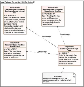
Figure 1 shows an example of the use of a SysML diagram to clarify three slightly conflicting original customer requirements. The first requirement calls for ventilation fans to keep running and damper doors to stay open for most areas on the rig during an internal fire. The second requirement calls for high-risk areas to stop fans and shut damper doors immediately. The third requirement calls for the machinery space to stop its fan when the fire alarm is released.
Although the original requirements do not clearly identify the machinery area as a high-risk area, we can conclude that the original intent was that the machinery area would be treated as a high-risk area. The strength of MBSE techniques is that we can now create a new clarified requirement to this effect, with an audit trail to all three original requirements and an attached note clarifying our reasoning.
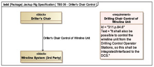
Figure 2 shows an example of defining a logical interface. The driller’s chair is required to be able to control the third-party wireline unit. As such, we can create a diagram and define exactly this logical interface. Notice that this particular diagram shows only the one interface we care about to the driller’s chair. By the time we are done modeling, the driller’s chair model in the database will have hundreds of interfaces. However, we don’t need to show them all in this particular diagram. We only need to show the one interface that we care about to satisfy the one requirement we are working on here. The modeling tool will take care of the bookkeeping in the database for us.
What Else Can be done With SysML and MBSE?
This sort of methodology and software tool chain can be used to model a wide variety of key assumptions about the system that is being built, including:
• Logical structure – what are the major functions of the system?
• Physical structure – how are they implemented in hardware?
• Test cases – how do test cases map to requirements and implementation?
• Parametric relationships – this kind of tool can be used to describe and model complex problems, like the location of the center of gravity on a ship
• Interfaces – interfaces can be modeled in great detail, including physical, electrical and software characteristics
• Behavior – behavior of the system, particularly of interfaces, can be modeled in detail.
Using the underlying model database, more advanced tools can also partially or fully generate source code for simulations, embedded systems and hardware-in-the-loop testing.
Who Uses MBSE?
Quite a few industries have adopted MBSE techniques in the last 20 years or so. The complexity of software automation tends to be a key driver. The approximate beginning of adoption of MBSE techniques in different industries is:
• Aerospace and defense – 1990s;
• Automotive – mid-2000s;
• Railway equipment providers – mid-2000s;
• Railway operators – mid-2000s; and
• Medical device makers – 2010+.
Technical leaders from these industries participate in INCOSE activities and share best practices.
Looking forward
Where should we go from here? Let’s look at jackups and drillships as an area of focus.
Is a Jackup Simpler than a Car?
Is a jackup simpler than a new Ford automobile? Table 1 puts Ford’s information side-by-side with parameters gleaned from Asatte Press’ current work with the shipyard. One approach to comparing these two sets of numbers would be to compare the 2,000 software requirements identified for the jackup so far with Ford’s 50,000 primary mechanical requirements.
The first conclusion one might draw is that the behavior of the jackup is much less complicated than the behavior of the car. However, it is unlikely that this conclusion would be correct. It is much more likely that the oil industry simply is not yet as proficient as Ford in describing in detail exactly what it is that the jackup (and all its onboard systems) are supposed to do.
Automation and the Pressures Facing the Industry
Let’s take a look at some key pressures facing the drilling industry:
• Great crew change – By some estimates, the drilling industry needs to replace almost half of its workforce in the next few years. It isn’t always easy to find young skilled workers who want to spend a career on a drilling rig;
• Drill faster – More wells need to be drilled in increasingly challenging environments to access remaining hydrocarbon reserves;
• Drill cheaper – Because more wells need to be drilled, they need to be drilled more cheaply;
• Drill better – The technical challenge of the wells is increasing;
• Drill cleaner – Less disruption to the environment; and
• Drill quieter – Literally less noise, but also less social disruption.
Almost anyone who is working on one of these challenges is telling the industry that software automation will play a major role in solving the problem. The oil industry can expect to see an explosion in the scope and complexity of software automation in the next 10 years.
Is Automation Making us Safer?
Software automation can help to solve an incredible range of problems. However, computers themselves are completely stupid. They will do only exactly what they are told and nothing else. Computers do not possess common sense.
If we are only clearly articulating requirements for 2,000/5,000 or about 4% of the required behavior of the system, the chances that the automation is really making us optimally safe are pretty low.
Getting Ahead of the Curve
The companies that will thrive on the coming explosion of software automation in the drilling industry will be the ones that can aggressively develop the expertise to specify precisely what it is that the automation systems need to do – at every level of complexity.
Further, this disciplined control of the complexity must start all the way at the beginning of the conception of a drilling rig design. Delegating requirements management to shipyards and a large group of suppliers will be a less and less successful strategy. Operators and drilling contractors must own the complexity and drive it.
The operators and drilling contractors that step up to the plate and take charge of this problem will be the owners of automation systems that work predictably and reliably in an emergency. They will also be owners of rigs that leave the yard ready for action on day one.
This article is based on a presentation at the 2014 IADC Advanced Rig Technology Conference & Exhibition, 16-17 September, Galveston, Texas.

