Real-time geosteering software enhances data sharing, updating to optimize well placement
By Richard Pelling, Doug Gilmour and Robert Innes, Paradigm
The twin challenges of finding and producing hydrocarbons from increasingly complex reservoirs while meeting tighter fiscal constraints drive the need for well path and engineering design optimization. Just as designing wells within a 3D geological model or seismic volume can shorten well-planning cycle times, improve well placement and reduce drilling risk, the ability to make real-time updates to those 3D models, based on petrophysical log responses, enables rapid and informed replanning and engineering while drilling.
This article describes an integrated software solution that helps optimize well placement and maximize production.
WORK FLOW
Key to the effectiveness of the solution is use of integrated, multidisciplinary tools operating on a shared data management, and interoperability framework that enables experts from drilling, geology, petrophysics and geophysics to work concurrently and share data.
Use of a geosteering solution in combination with a unified well planning and drilling engineering application delivers a work flow that supports creation of log-scale geosteering models ahead of drilling, facilitates interactive updates to geosteering models while drilling, and enables rapid re-planning of wells using updated models.
Where real-time data feeds are available from the rig site, this work can be carried out in a real-time center, enabling an expert multidisciplinary team to evaluate operational decisions.
WELL PLANNING
A 3D geological model, defined in industry-standard file formats, is shared by the engineering and geosteering applications. In the engineering application, the well is planned and fully engineered within the context of the 3D model, allowing geological validation of the wellbore at every stage of the design process. Using 3D pressure volumes, pore and fracture data can be extracted along the well and used to validate casing depths and optimize drilling hydraulics. The final well design is then shared with the geosteering application.

LOG-SCALE GEOSTEERING
By combining the overall structural framework provided by an existing 3D geological model with the detailed log responses observed in offset well(s) that penetrate the formations of interest, forward modeling in the true stratigraphic thickness domain can be used to produce a detailed pre-drill model along the planned wellbore that reflects predicted changes in log character.
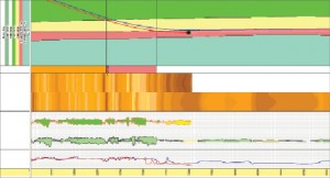
This can include the modeling of tools from any contractor. Typically displayed as a slice or curtain in distance out along the well path, this pre-drill log property model becomes the backdrop upon which new information is displayed as it is received during the drilling operation (Figure 1).
In addition to providing predicted log values, a full property map can also be generated (Figure 2). By using 3D surfaces, property values can be predicted at any point along the wellbore to produce 3D-modeled image logs. If sufficient changes in log character exist to determine that the well is approaching a given formation, this can be used to geosteer the well to optimize entry and/or avoid early exit from the target reservoir.
DRILLING, GEOSTEERING
As drilling progresses, timely incorporation of new data into the model is essential. Historically, this data has come in the form of individual files from the contractor or via a proprietary real-time data source. Today, where available, Wellsite Information Transfer Standard Markup Language (WITSML) provides an open standard format for real-time data transmission that can be automatically streamed into both the engineering and geosteering applications via a real-time data acquisition system.
By dispensing with the previous practice of manually loading individual files when new data arrive, this automated approach increases efficiency and reduces the chance of transcription errors. The actual well position and positional uncertainty are calculated and visualized in the 3D model and compared with the planned well. Actual logging-while-drilling (LWD) logs are displayed and compared with the predicted logs.
Discrepancies between the pre-drill model and actual results can result from a number of sources. Using local knowledge of the reservoir, it is usually possible to reconcile the differences and incorporate this information into the existing model.
In some cases, the original structural framework may be off-depth, while in others the log character of a given formation at a given point may be different from what is expected. By interactively editing the pre-drill model, the geosteering user can reconcile differences between predicted and actual responses. The user has the ability to interactively alter the dip of a given bed, alter its thickness or insert a fault and see instantly how these changes would affect the modeled log properties. Additionally, geological constraints regarding conformability of surfaces from the initial model will be honored during editing operations. Undesirable edits can be removed and an alternative edit made. There are often several possible interpretations of the types of situation we see while geosteering.
Here, the aim is to provide the user with sufficiently flexible tools to try several “what if” scenarios, and apply local knowledge to select the most probable scenario prior to making any decisions.

In parallel, the directional driller can use the engineering application to monitor drilling progress against plan, calibrate friction factors and project ahead from the real-time bit position to ensure that the well can be drilled based on defined dogleg constraints. Additionally, engineering analysis can be run on the replanned interval to ensure that the well is drillable from mechanical and hydraulic perspectives, and that the casing or completion string can be installed.
Where applicable, the anti-collision scan can be run simultaneously to ensure the well will not collide with any existing wells in the area.
Differences between the predicted and actual logs signal changes in geology, and indicate that the model needs to be updated. Updates are achieved through interactive picking of formation intersections and changing formation dip or bed thickness until the log responses match.
Large discrepancies may be explained by drilling through a fault and can be incorporated into the model. Where model updates result in significant true vertical depth adjustments, the updated 3D surfaces can be used in the engineering application to replan and re-engineer the well, during drilling, based on the most recent petrophysical interpretation (Figure 3). If required, a sidetrack can be created in the engineering application, a new 3D model produced and the geosteering process repeated for the planned sidetrack.
Post-well correlation of existing wells can be performed to update regional-scale geological models and optimize the logging program for future wells.
FIELD USE
The work flows described in this article have been used extensively. Mitra et al (2004) described the use of this workflow in the redevelopment of ONGC’s Mumbai High oilfield, which features complex multilayered carbonate reservoirs necessitating high-tech horizontal wells.
They noted that, in addition to improving the success of placement of individual wells, they were also able to reduce nonproductive time and the overall cost of the wells.
The work flow has now been used globally in onshore and offshore situations in a variety of reservoirs ranging from deepwater clastic reservoirs to Mid-continent tight-gas plays such as the Barnett Shale.
References: Mitra, P.P., Joshi, T.R. & Thevoux-Chabuel (2004), “Real Time Geosteering of High Tech Well in Virtual Reality and Prediction Ahead of Drill Bit for Cost Optimization and Risk Reduction in Mumbai High L-III Reservoir,” SPE 88531, SPE Asia Pacific Oil and Gas Conference and Exhibition, 18-20 October, Perth, Australia.


One Comment