Innovative configuration helps industry tap into the potential of riserless intervention systems
Strategic placement of downlines, vessel positions must be understood to ensure successful deployment, minimize downtime
By Mahesh Sonawane and Ben Toleman, 2H Offshore
Subsea well intervention is akin to the regular maintenance of a car. While it can feel like an inconvenience to get it serviced, it is essential for the longevity and performance of the car. Similarly, offshore wells deplete over time and encounter issues that hamper oil production. In order to restore peak performance, well intervention is necessary.
There are economic benefits to an intervention operation, as increased well production boosts revenue and offsets the cost of the intervention operation. Still, there is a desire in the industry to minimize maintenance and reduce the cost of well intervention. Enter riserless well intervention: Gaining traction in the Gulf of Mexico in recent years, riserless light well intervention (RWLI) has become an attractive option for operators. Globally, the RLWI market is expected to grow at a rate of 5.2% from 2020 to 2027, reaching $2.5 billion. The market is being driven by the increasing demand for oil and gas, subsea exploration and production, and RLWI’s cost effectiveness compared with traditional riser-based methods.
While riser-based intervention is a robust solution, it is often more time-consuming and expensive due to the need for a dedicated riser system, intervention package and a vessel capable of handling a riser.
Riserless mechanical or hydraulic intervention systems, on the other hand, can be operated from smaller vessels of opportunity and can be accomplished in a faster time frame.
Riser-based intervention systems offer the advantage of having a standardized riser system, available from various OEMs, which simplifies and reduces the need for system integration. Riserless downline intervention systems, in contrast, do not come as standard solutions; they require meticulous planning, a system integration approach and customized well-specific solutions. So, where a riser-based intervention is analogous to purchasing an off-the-shelf product from a big box retailer, a riserless system is more akin to shopping on Etsy, where customization and unique solutions are key.
This article explores the elements of mechanical and hydraulic riserless intervention systems and provide an overview of the various options. Configuration and essential optimization will be discussed, as well as the system level analyses required to mitigate operational challenges encountered while deploying this system offshore. Typical downlines in a riserless system can include:
- Circulation downlines.
- Flexible flying leads from downline to the well.
- Control umbilical and umbilical termination assembly.
- Mechanical intervention wireline.
- Subsea intervention package.
- Passive disconnect mechanism for the circulation line and umbilical.
Circulation lines
The circulation line for pumping fluids can be either coiled tubing or small-diameter drill pipe. Depending on the requirement of the operation, there may be one or two circulation lines. For coiled tubing, the pipe can be deployed through an injector head or over a turn-down sheeve. If using circulation lines made of drill pipe with threaded connections, and the rig is equipped to handle and run drill pipe, the circulation lines are deployed to a depth of 100-200 ft above the mud line. At this depth, a clump weight can be employed to maintain the line in tension and prevent excessive movement due to environmental loads, such as currents and waves. To complete the circulation loop, a flexible hose is deployed from the base of the coiled tubing or drill pipe to the well. This flexible hose provides some compliance in the system, allowing the vessel to move within a certain distance from the well without imposing mechanical loads on the subsea tree or well architecture.
Flexible hose from downline to the well
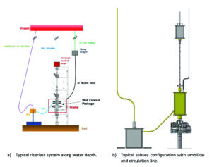
The flexible hose can be a bonded or unbonded flexible pipe, or a composite pipe. Depending on pipe’s weight and bending stiffness, it is necessary to evaluate the catenary shape the flexible pipe will adopt when deployed in water.
The pipe may form a J-shaped or U-shaped catenary with a sag bend as shown in Figure 3. This configuration is acceptable if the stab-in angle with the subsea tree is orientated downward relative to the horizontal. If the stab-in angle is vertical, buoyancy may be required to help the pipe float and maintain a vertical stab-in angle. In some cases, a swivel may be required at the subsea connection to prevent excessive bending or torsional loads on the flexible pipe.
Control umbilical & umbilical termination assembly
A control umbilical is essential for providing hydraulic and electrical power to the subsea intervention equipment. It can be deployed in various ways. If the umbilical is sufficiently robust to support its own weight over thousands of feet of water depth, it can be deployed independently. Alternatively, the control umbilical can be deployed using a wireline, with clamps spaced at sufficient interval to support the umbilical’s weight. The umbilical is deployed along with the umbilical termination assembly.
In certain configurations, if supported by a wireline, the umbilical termination assembly can hang freely with its weight supported by the wireline. On the other hand, a mud mat may be deployed in the vicinity of the well and the umbilical termination assembly landed onto it. This requires sufficient sag or catenary in the umbilical to prevent it from exerting excessive loads on the mud mat or lifting the umbilical termination assembly off the mud mat due to environmental loads and vessel motions.
Mechanical intervention wireline & subsea intervention package
The mechanical intervention system consists of the pressure control head, lubricators, subsea intervention package, wireline and tool string. The lubricator can be quite tall, ranging from 50-90 ft in height, standing freely on the intervention package. The wireline and tool string deployed within the lubricator must have adequate headroom to perform the operations and accommodate for environmental loads and vessel motions. Insufficient headroom can cause the wireline to pull on the lubricator valve, leading to excessive bending loads on the subsea equipment and the well.
Passive disconnect mechanism for circulation line & umbilical
Drilling risers and intervention riser systems are equipped with an active emergency disconnect system (EDS) that can disconnect the riser from the well in emergencies, such as vessel blackout and loss of position. The riserless downline systems, on the other hand, primarily rely on passive systems, though they may occasionally include an active disconnect system. A passive EDS is a trigger mechanism designed to break at a specific rated load, disconnecting the downline from the well to prevent excessive loading on the subsea tree or well architecture. This can take the form of a shear pin, a notched bolt or a guillotine that can shear the flexible hose or umbilical for disconnection.
It is crucial that the passive disconnect mechanisms are designed to a specification that ensure safe operations by disconnecting the intervention system when the well is at risk. However, these systems must also be calibrated to avoid accidental triggers or false alarms, which could disrupt regular operations in more benign day-to-day environments.
System optimization
Traditionally, different downlines were considered as individual elements, each configured based on its own performance. In addition, each system’s analysis was the responsibility of its respective OEM. However, this approach does not always produce the best outcome, as the system needs to be integrated to provide the most efficient and safe solution for the operator or end user, minimizing downtime and maximizing safety.
Once the downline options have been selected, based on the specifications of the operations, the first step in system integration is conducting a system-level analysis to fine-tune the geometries, configurations and deployment locations from the vessel. Optimizing the configuration of different downlines is a key step and can prevent over 90% of potential operational issues.
A key decision for the coil-tubing downline is the deployment location on the vessel. For a mechanical intervention that includes a wireline system, the vessel must be positioned directly above the well center. However, the coil tubing can be deployed from the edge of the moonpool, through the moonpool, from the side of the vessel, or from the aft of the vessel. This depends on the vessel’s deck layout. Once the deployment location is finalized, the next considerations are whether a clump weight is required, how much it should weigh, its elevation from the mudline, and the associated length of the flexible hose. A heavy clump weight will minimize displacement of the coil-tubing pipe and reduce the stresses. However, there is a preference for the smallest possible clump weight to ease handling.
The next step in the optimization process is to size and specify the breakaway load rating of the passive disconnect mechanism. The passive EDS protects the downline equipment and the well equipment in case of emergencies.
After all downline configurations have been selected, a global model of the entire system can be built and preliminary analysis conducted for a range of vessel movements relative to its nominal position going toward the well, away from, and perpendicular to the well.
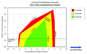
In addition, a range of environmental currents and wave loading should be analyzed. This analysis determines the loads and behavior of all downlines, allowing for development of a safe operating window within which all downlines can operate safely. At the boundaries of this window, the passive disconnect system should safely disengage the downlines from the well. Upon completion of this assessment, a safe operating zone or operating window will be established for the integrated downline system. An example of an operating window is shown in Figure 2.
Conclusion
The effectiveness of downlines in a riserless well intervention setup is intricately linked to the initial configuration and nominal settings. Utilizing a global model allows for better understanding of how coiled tubing characteristics affect flexible jumper configurations and how different downlines interact. The strategic placement of vessel positions and downline deployment locations plays a crucial role in managing the bend radius of flexible hoses and the surface stress on coiled tubing
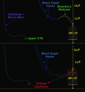
To enhance operability and minimize downtime, it’s important to optimize vessel positions for various environmental scenarios, adjust clump weight elevation to manage hose slack, and use buoyancy modules effectively based on flexible stab-in angles. These measures collectively improve the efficiency and reliability of subsea operations. DC